FRONT STABILIZER BAR (for 2GR-FE) INSTALLATION

-
INSTALL NO. 1 FRONT STABILIZER BAR BUSHING
-
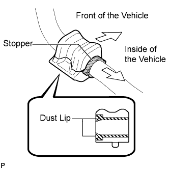
Install the 2 No. 1 front stabilizer bar bushings to the front stabilizer bar.
Note
-
Install the No. 1 front stabilizer bar bushing so that the dust lips face outward of the vehicle.
-
Install the No. 1 front stabilizer bar bushing so that the cutouts face rearward of the vehicle.
-
-
-
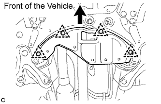
INSTALL FRONT STABILIZER BAR
-
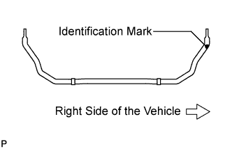
Install the front stabilizer bar to the front suspension crossmember so that the identification mark is positioned on the right side of the vehicle.
-
-
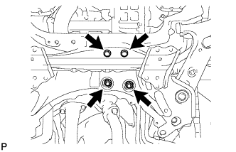
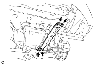
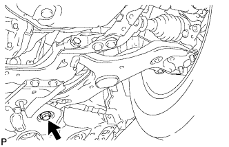
INSTALL FRONT SUSPENSION MEMBER FRONT BRACE LH
-
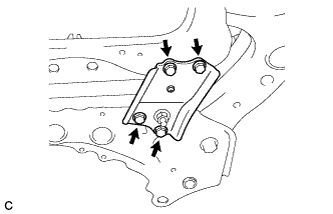
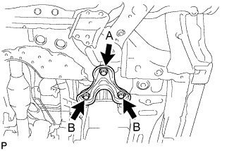
Install the front suspension member front brace LH with the 4 bolts.
- Torque:
- 87 N*m { 887 kgf*cm, 64 ft.*lbf }
Tech Tips
After installing the front suspension member front brace LH, make sure that the protrusion of the No. 1 front stabilizer bar bushing comes out.
-
-
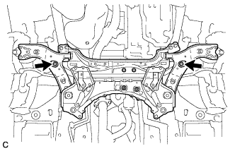
INSTALL FRONT SUSPENSION MEMBER FRONT BRACE RH
Tech Tips
Perform the same procedure as for the LH side.
-
INSTALL FRONT LOWER SUSPENSION ARM SUB-ASSEMBLY LH
-
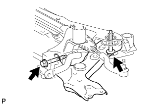
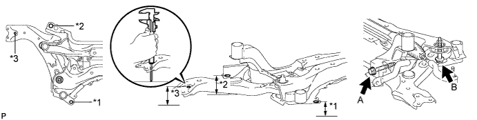
Temporarily install the front lower suspension arm sub-assembly LH to the front suspension crossmember sub-assembly with the 2 bolts and the nut.
-
Position the front suspension crossmember sub-assembly on a level surface.
-
Using a vernier caliper, measure height *1 and *2.
Note
Position the crossmember with the front suspension member braces LH and RH mounted.
-
Check that height *2 is lower than *1 by 10 mm.
-
Position the front lower suspension arm so that height *3 is the same as *1.
-
Tighten the bolt A.
- Torque:
- 233 N*m { 2376 kgf*cm, 172 ft.*lbf }
-
-
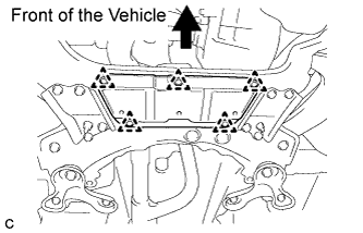
INSTALL FRONT SUSPENSION CROSSMEMBER SUB-ASSEMBLY
-
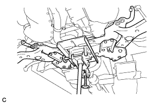
Raise the front suspension crossmember sub-assembly with a transmission jack.
-
Temporarily install the front suspension crossmember sub-assembly with 2 bolts.
-
Temporarily install the front suspension crossmember sub-assembly to the rear engine mounting insulator with the 2 bolts and 2 nuts.
-
Temporarily install the front suspension member brace sub-assemblies LH and RH with 2 bolts A and the 4 bolts B.
-
Alternately insert SST into the positioning holes on the front suspension crossmember RH and LH while tightening the bolts on the LH and RH sides to specified torque using several steps.
- SST
- 09670-00010
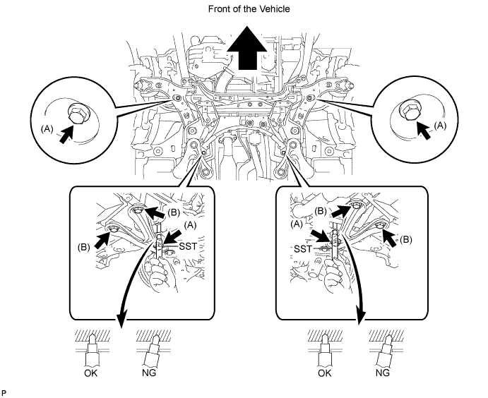
- Torque:
- Bolt (A)
- 137 N*m { 1397 kgf*cm, 101 ft.*lbf }
- Bolt (B)
- 93 N*m { 948 kgf*cm, 69 ft.*lbf }
-
Fully tighten the 2 bolts and 2 nuts.
- Torque:
- 95 N*m { 969 kgf*cm, 70 ft.*lbf }
-
-
CONNECT FRONT LOWER SUSPENSION ARM SUB-ASSEMBLY LH
-
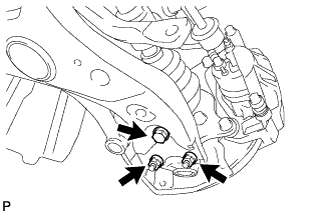
Connect the front lower suspension arm sub-assembly LH to the ball joint with the bolt and 2 nuts.
- Torque:
- 93 N*m { 948 kgf*cm, 69 ft.*lbf }
-
-
CONNECT FRONT LOWER SUSPENSION ARM SUB-ASSEMBLY RH
Tech Tips
Perform the same procedure as for the LH side.
-
CONNECT TIE ROD END SUB-ASSEMBLY LH
-
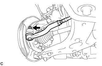
Connect the tie rod end sub-assembly LH to the steering knuckle with the nut.
- Torque:
- 49 N*m { 500 kgf*cm, 36 ft.*lbf }
Note
Further tighten the nut up to 60° if the holes for the cotter pin are not aligned.
-
Install a new cotter pin.
-
-
CONNECT TIE ROD END SUB-ASSEMBLY RH
Tech Tips
Perform the same procedure as for the LH side.
-
CONNECT NO. 2 STEERING INTERMEDIATE SHAFT ASSEMBLY
-
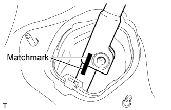
Align the matchmarks on the No. 2 steering intermediate shaft assembly and the steering intermediate shaft assembly.
-
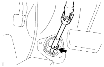
Connect the No. 2 steering intermediate shaft assembly to the steering intermediate shaft assembly, and install the bolt.
- Torque:
- 35 N*m { 360 kgf*cm, 26 ft.*lbf }
-
-
INSTALL COLUMN HOLE COVER SILENCER SHEET
-
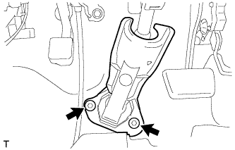
Install the column hole cover silencer sheet with the 2 clips.
-
-
INSTALL FRONT STABILIZER LINK ASSEMBLY LH
-
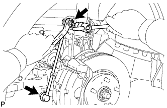
Install the front stabilizer link assembly LH with the 2 nuts.
- Torque:
- 74 N*m { 755 kgf*cm, 55 ft.*lbf }
Note
If the ball joint turns together with the nut, use a hexagon wrench (6 mm) to hold the stud bolt.
-
-
INSTALL FRONT STABILIZER LINK ASSEMBLY RH
Tech Tips
Perform the same procedure as for the LH side.
-
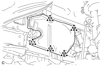
INSTALL FRONT SUSPENSION MEMBER REINFORCEMENT LH
-
Install the front suspension member reinforcement LH with the 4 bolts.
- Torque:
- 96 N*m { 979 kgf*cm, 71 ft.*lbf }
-
-
INSTALL FRONT SUSPENSION MEMBER REINFORCEMENT RH
Tech Tips
Perform the same procedure as for the LH side.
-
INSTALL REAR ENGINE UNDER COVER LH
-
Install the rear engine under cover LH with the 5 clips.
-
-
INSTALL REAR ENGINE UNDER COVER RH
Tech Tips
Perform the same procedure as for the LH side.
-
INSTALL ENGINE UNDER COVER
-
INSTALL NO. 1 ENGINE UNDER COVER
-
INSTALL NO. 2 ENGINE UNDER COVER (for Front Side)
-
Install the No. 2 engine under cover with the 5 clips.
-
-
INSTALL NO. 2 ENGINE UNDER COVER (for Rear Side)
-
Install the No. 2 engine under cover with the 4 clips.
-
-
INSTALL FRONT WHEELS
- Torque:
- 103 N*m { 1050 kgf*cm, 76 ft.*lbf }
-
STABILIZE SUSPENSION
-
Lower the vehicle and bounce it up and down several times to stabilize the front suspension. Raise the vehicle.
-
-
FULLY TIGHTEN FRONT LOWER SUSPENSION ARM SUB-ASSEMBLY LH
-
Fully tighten the bolt.
- Torque:
- 214 N*m { 2182 kgf*cm, 158 ft.*lbf }
Note
When tightening the bolt, keep the nut from rotating.
-
-
INSPECT AND ADJUST FRONT WHEEL ALIGNMENT
Tech Tips
Inspect and adjust front wheel alignment Click here.