FRONT STABILIZER BAR (for 2AZ-FE) INSTALLATION

-
INSTALL NO. 1 FRONT STABILIZER BAR BUSHING
-
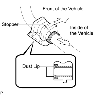
Install the 2 No. 1 front stabilizer bar bushings to the front stabilizer bar.
Note
-
Install the No. 1 front stabilizer bar bushing so that the dust lips face outward of the vehicle.
-
Install the No. 1 front stabilizer bar bushing so that the cutouts face rearward of the vehicle.
-
-
-
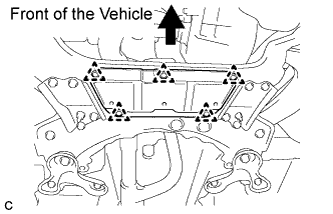
INSTALL FRONT STABILIZER BAR
-
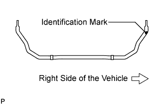
Install the front stabilizer bar to the front suspension crossmember so that the identification mark is positioned on the right side of the vehicle.
-
-
INSTALL FRONT SUSPENSION MEMBER FRONT BRACE LH
-
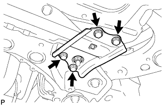
Install the front suspension member front brace LH with the 4 bolts.
- Torque:
- 87 N*m { 887 kgf*cm, 64 ft.*lbf }
Tech Tips
After installing the front suspension member front brace LH, make sure that the protrusion of the No. 1 front stabilizer bar bushing comes out.
-
-
INSTALL FRONT SUSPENSION MEMBER FRONT BRACE RH
Tech Tips
Perform the same procedure as for the LH side.
-
TEMPORARILY TIGHTEN FRONT LOWER SUSPENSION ARM SUB-ASSEMBLY RH
-
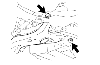
Temporarily install the front lower suspension arm sub-assembly RH to the front suspension crossmember sub-assembly with the 2 bolts and nut.
-
-
CONNECT FRONT LOWER SUSPENSION ARM SUB-ASSEMBLY RH
-
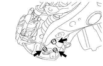
Install the front lower suspension arm sub-assembly RH to the front lower ball joint with the bolt and 2 nuts.
- Torque:
- 93 N*m { 948 kgf*cm, 69 ft.*lbf }
-
-
INSTALL FRONT STABILIZER LINK ASSEMBLY LH
-
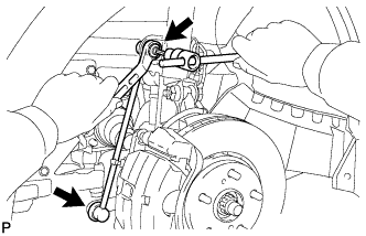
Install the front stabilizer link assembly LH with the 2 nuts.
- Torque:
- 74 N*m { 755 kgf*cm, 55 ft.*lbf }
Note
If the ball joint turns together with the nut, use a hexagon wrench (6 mm) to hold the stud bolt.
-
-
INSTALL FRONT STABILIZER LINK ASSEMBLY RH
Tech Tips
Perform the same procedure for as the LH side.
-
INSTALL NO. 2 ENGINE UNDER COVER (for Front Side)
-
Install the No. 2 engine under cover with the 5 clips.
-
-
INSTALL FRONT WHEELS
- Torque:
- 103 N*m { 1050 kgf*cm, 76 ft.*lbf }
-
STABILIZE SUSPENSION
-
Lower the vehicle and bounce it up and down several times to stabilize the front suspension. Raise the vehicle.
-
-
FULLY TIGHTEN FRONT LOWER SUSPENSION ARM SUB-ASSEMBLY RH
-
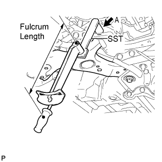
Using SST to fully tighten the bolt A.
- SST
- 09961-01270
- Torque:
- without SST
- 233 N*m { 2376 kgf*cm, 172 ft.*lbf }
- with SST
- 158 N*m { 1615 kgf*cm, 116 ft.*lbf }
Note
-
Use a torque wrench with a fulcrum length of 425 mm (16.73 in.).
-
This torque value is effective when SST is parallel to the torque wrench.
-
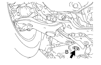
Fully tighten the bolt B while holding the nut.
- Torque:
- 214 N*m { 2182 kgf*cm, 158 ft.*lbf }
Note
Because the nut has its own stopper, do not turn the nut. Tighten the bolt with the nut secured.
-
-
INSPECT AND ADJUST FRONT WHEEL ALIGNMENT
Tech Tips
Inspect and adjust the front wheel alignment Click here.