VEHICLE STABILITY CONTROL SYSTEM, Diagnostic DTC:C1267/67

| DTC Code | DTC Name |
|---|---|
| C1267/67 | Brake Pedal Load Sensing Switch |
DESCRIPTION
The brake pedal load sensing switch is turned on when the brake pedal is depressed with force exceeding a predetermined level.
The skid control ECU detects if the brake pedal is depressed or not via this circuit.
| DTC No. | DTC Detection Condition | Trouble Area |
|---|---|---|
| C1267/67 | When any of the following is detected:
|
|
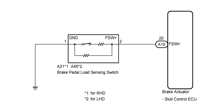
WIRING DIAGRAM
INSPECTION PROCEDURE
Tech Tips
When C1249/49 is output together with C1267/67, inspect and repair the trouble areas indicated by C1249/49 first Click here.
PROCEDURE
-
READ VALUE USING INTELLIGENT TESTER (STOP LIGHT SWITCH AND BRAKE PEDAL LOAD SENSING SWITCH)
-
Connect the intelligent tester to the DLC3.
-
Turn the engine switch on (IG).
-
Select the Data List mode on the intelligent tester Click here.
ABS/VSC/TRC Tester Display Measurement Item / Range Normal Condition Diagnostic Note Stop Light SW Stop light switch / ON or OFF ON: Brake pedal depressed
OFF: Brake pedal released
- Brake Pedal Load Sensing SW Brake pedal load sensing switch / ON or OFF ON: Brake pedal depressed beyond the specified point
OFF: Brake pedal not depressed beyond the specified point
- -
Check that the stop light switch display and brake pedal load sensing switch display observed on the intelligent tester change according to brake pedal operation.
OK The intelligent tester displays ON or OFF according to brake pedal operation. -
Slowly depress the brake pedal, and check when the stop light switch and brake pedal load sensing switch turn on.
OK First the stop light switch should turn on, and then the brake pedal load sensing switch should turn on. Result Result Proceed to OK A NG (The brake pedal load sensing switch does not turn on) B NG (The brake pedal load sensing switch turns on first) C
B 
INSPECT BRAKE PEDAL LOAD SENSING SWITCH Click here
C
CHECK BRAKE PEDAL AND STOP LIGHT SWITCH INSTALLATION Click here
A 
-
-
RECONFIRM DTC
-
Turn the engine switch off.
-
Clear the DTCs Click here.
-
Start the engine.
-
Perform a road test.
-
Check if the same DTC is recorded Click here.
Result Result Proceed to DTC (C1267/67) is not output A DTC (C1267/67) is output B
B 
REPLACE BRAKE ACTUATOR ASSEMBLY Click here
A 
CHECK FOR INTERMITTENT PROBLEMS (SYMPTOM SIMULATION) Click here
-
-
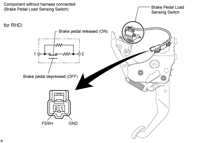
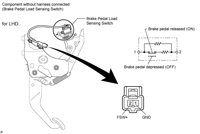
INSPECT BRAKE PEDAL LOAD SENSING SWITCH
Note
-
Do not remove the brake pedal load sensing switch from the brake pedal support assembly.
-
When there is a malfunction in the brake pedal load sensing switch, replace the brake pedal support assembly.
-
Turn the engine switch off.
-
Make sure that there is no looseness at the locking part and the connecting part of the connector.
-
Disconnect the brake pedal load sensing switch connector.
-
Measure the resistance according to the value(s) in the table below.
Standard Resistance Tester Connection Switch Condition Specified Condition 2 (FSW+) - 1 (GND) Brake pedal load sensing switch off
(Brake pedal depressed)
950 to 1050 Ω 2 (FSW+) - 1 (GND) Brake pedal load sensing switch on
(Brake pedal released)
203 to 223 Ω
NG
REPLACE BRAKE PEDAL SUPPORT ASSEMBLY (BRAKE PEDAL LOAD SENSING SWITCH) Click here
OK
-
-
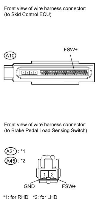
CHECK HARNESS AND CONNECTOR (SKID CONTROL ECU - BRAKE PEDAL LOAD SENSING SWITCH)
-
Make sure that there is no looseness at the locking part and the connecting part of the connector.
-
Disconnect the skid control ECU connector.
-
Measure the resistance according to the value(s) in the table below.
Standard Resistance for RHD Tester Connection Condition Specified Condition A10-20 (FSW+) - A21-2 (FSW+) Always Below 1 Ω A10-20 (FSW+) - Body ground Always 10 kΩ or higher A21-1 (GND) - Body ground Always Below 1 Ω for LHD Tester Connection Condition Specified Condition A10-20 (FSW+) - A45-2 (FSW+) Always Below 1 Ω A10-20 (FSW+) - Body ground Always 10 kΩ or higher A45-1 (GND) - Body ground Always Below 1 Ω
NG
REPAIR OR REPLACE HARNESS OR CONNECTOR
OK
REPLACE BRAKE ACTUATOR ASSEMBLY Click here
-
-
CHECK BRAKE PEDAL AND STOP LIGHT SWITCH INSTALLATION
-
Turn the engine switch off.
-
Check the brake pedal height and stop light switch installation Click here.
OK The brake pedal height and stop light switch installation are normal.
NG
ADJUST BRAKE PEDAL OR STOP LIGHT SWITCH Click here
OK
REPLACE BRAKE PEDAL SUPPORT ASSEMBLY (BRAKE PEDAL LOAD SENSING SWITCH) Click here
-