VEHICLE STABILITY CONTROL SYSTEM VSC OFF Indicator Light Remains ON
DESCRIPTION
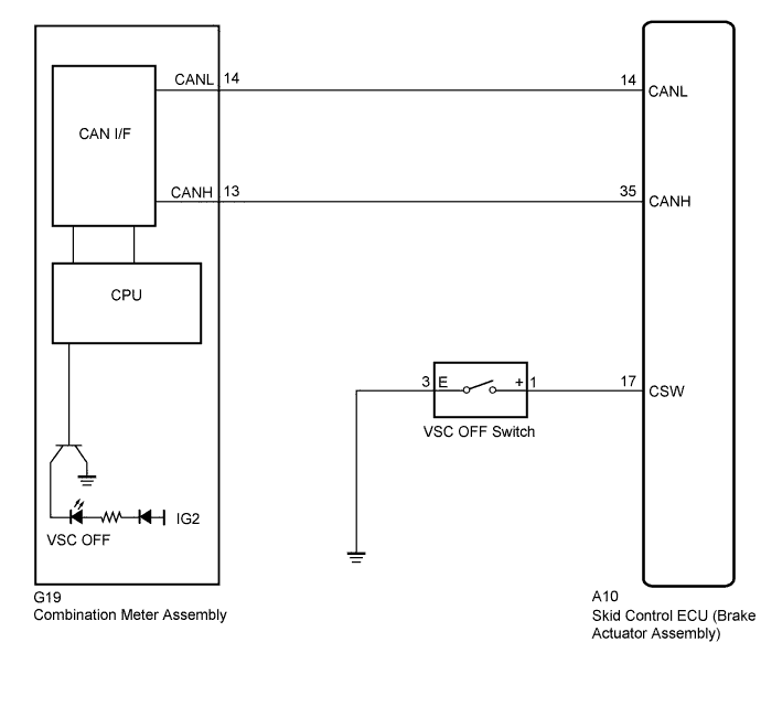
The skid control ECU is connected to the combination meter assembly via CAN communication.
Pressing the VSC OFF switch turns off traction control and pressing and holding this switch turns off traction and VSC controls. If VSC control turns off, the VSC OFF indicator light will come on.
WIRING DIAGRAM
INSPECTION PROCEDURE
PROCEDURE
-
CHECK CAN COMMUNICATION SYSTEM
-
Check if the CAN communication system DTC is output Click here.
Result Result Proceed to DTC is not output A DTC is output B
B 
INSPECT CAN COMMUNICATION SYSTEM Click here
A 
-
-
CHECK IF SKID CONTROL ECU CONNECTOR IS SECURELY CONNECTED
-
Check if the skid control ECU connector is securely connected.
OK The connector is securely connected.
NG
CONNECT CONNECTOR TO ECU CORRECTLY
OK
-
-
CHECK BATTERY
-
Check the battery voltage.
Standard Voltage 11 to 14 V Result Result Proceed to OK A NG (for 2GR-FE) B NG (for 2AZ-FE) C
B
CHECK OR REPLACE CHARGING SYSTEM OR BATTERY (2GR-FE) Click here
C
CHECK OR REPLACE CHARGING SYSTEM OR BATTERY (2AZ-FE) Click here
A
-
-
INSPECT SKID CONTROL ECU (CSW TERMINAL)
-
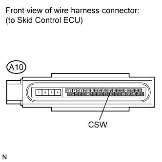
Disconnect the skid control ECU connector.
-
Measure the resistance according to the value(s) in the table below.
Standard Resistance Tester Condition Switch Condition Specified Condition A10-17 (CSW) - Body ground VSC OFF Switch OFF (Not pressed) 10 kΩ or higher
NG 
INSPECT VSC OFF SWITCH Click here
OK
-
-
INSPECT COMBINATION METER ASSEMBLY
-
Reconnect the skid control ECU connector.
-
Perform the Active Test of the combination meter assembly using the intelligent tester Click here.
-
Check the combination meter assembly.
OK The VSC OFF indicator light turns on or off in accordance with the intelligent tester operation. Tech Tips
If troubleshooting has been carried out according to the Problem Symptoms Table, refer back to the table and proceed to the next step before replacing the part Click here.
NG
REPLACE COMBINATION METER ASSEMBLY Click here
OK 
REPLACE BRAKE ACTUATOR ASSEMBLY Click here
-
-
INSPECT VSC OFF SWITCH
-
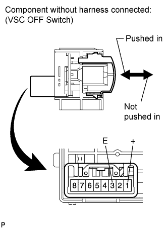
Disconnect the VSC OFF switch connector.
-
Measure the resistance according to the value(s) in the table below.
Standard Resistance Tester Connection Switch Condition Specified Condition 1 (+) - 3 (E) Switch is pushed in Below 1 Ω 1 (+) - 3 (E) Switch is not pushed in 10 kΩ or higher
NG
REPLACE VSC OFF SWITCH Click here
OK
-
-
CHECK HARNESS AND CONNECTOR (SKID CONTROL ECU - VSC OFF SWITCH)
-
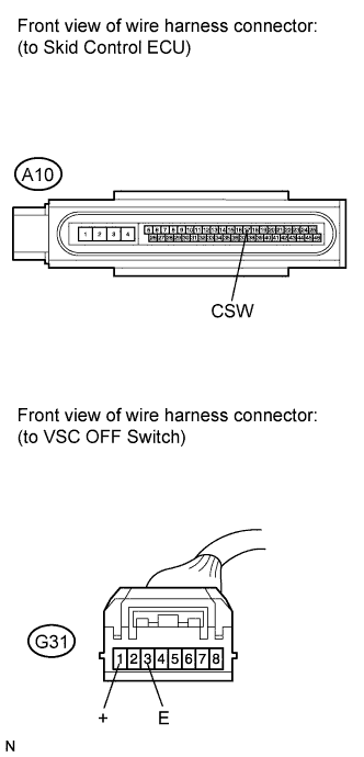
Measure the resistance according to the value(s) in the table below.
Standard Resistance Tester Connection Condition Specified Condition A10-17 (CSW) - G31-1 (+) Always Below 1 Ω A10-17 (CSW) - Body ground Always 10 kΩ or higher G31-3 (E) - Body ground Always Below 1 Ω Tech Tips
If troubleshooting has been carried out according to the Problem Symptoms Table, refer back to the table and proceed to the next step Click here.
NG
REPAIR OR REPLACE HARNESS OR CONNECTOR
OK
REPLACE BRAKE ACTUATOR ASSEMBLY Click here
-