STEERING KNUCKLE INSTALLATION

-
INSTALL FRONT AXLE HUB SUB-ASSEMBLY
-
Secure the front axle assembly between aluminum plates in a vise.
Note
Do not overtighten the vise.
-
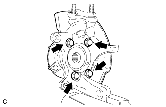
Install the front axle hub sub-assembly and dust cover with the 4 bolts.
- Torque:
- 96 N*m { 979 kgf*cm, 71 ft.*lbf }
-
-
INSTALL FRONT LOWER BALL JOINT
-
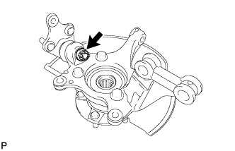
Install the front lower ball joint assembly to the front axle hub assembly with the nut.
- Torque:
- 133 N*m { 1356 kgf*cm, 98 ft.*lbf }
Note
Ensure that the threads and tapered areas are free of oil or other foreign matter.
-
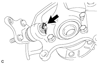
Install a new clip to the front lower ball joint assembly.
Note
Further tighten the nut up to 60° if the holes for the clip are not aligned.
-
-
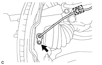
INSTALL FRONT AXLE ASSEMBLY
-
Align the front axle assembly with the splines of the front drive shaft assembly, and then insert the front drive shaft assembly into the front axle assembly.
Note
-
Do not deform the dust cover.
-
Do not damage the outboard joint boot and speed sensor rotor.
-
Make sure to keep the speed sensor rotor and its installation surfaces free of foreign matter.
-
-
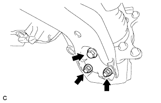
Install the front axle assembly to the front shock absorber with the 2 bolts and 2 nuts as shown in the illustration.
- Torque:
- 240 N*m { 2447 kgf*cm, 177 ft.*lbf }
-
-
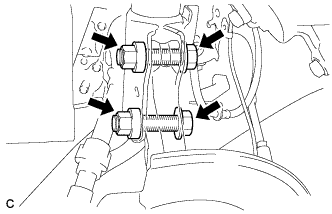
CONNECT FRONT LOWER SUSPENSION ARM SUB-ASSEMBLY
-
Connect the front lower suspension arm sub-assembly to the front lower ball joint with the bolt and 2 nuts.
- Torque:
- 93 N*m { 948 kgf*cm, 69 ft.*lbf }
-
-
CONNECT TIE ROD END SUB-ASSEMBLY
-
Connect the tie rod end sub-assembly LH to the steering knuckle with the nut.
- Torque:
- 49 N*m { 500 kgf*cm, 36 ft.*lbf }
Note
Further tighten the nut up to 60° if the holes for the cotter pin are not aligned.
-
Install a new cotter pin.
-
-
INSTALL FRONT DISC
-
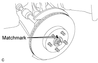
Align the matchmarks of the disc and axle hub, and install the disc.
Note
When installing a new disc, select the installation position where the front disc has minimal runout.
-
-
CONNECT FRONT DISC BRAKE CALIPER ASSEMBLY
-
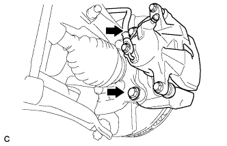
Install the front disc brake caliper assembly to the steering knuckle with the 2 bolts.
- Torque:
- 98 N*m { 999 kgf*cm, 72 ft.*lbf }
-
-
CONNECT FRONT SPEED SENSOR
-
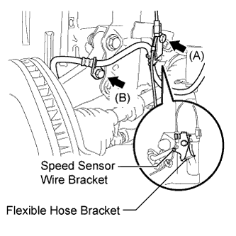
Connect the flexible hose bracket and speed sensor wire bracket with the bolt (A).
- Torque:
- 19 N*m { 194 kgf*cm, 14 ft.*lbf }
Note
Connect the flexible hose bracket first.
-
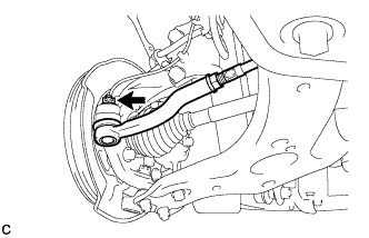
Connect the flexible hose to the steering knuckle with the bolt (B).
- Torque:
- 19 N*m { 194 kgf*cm, 14 ft.*lbf }
-
Install the front speed sensor to the steering knuckle with the bolt and clamp.
- Torque:
- 8.5 N*m { 87 kgf*cm, 75 in.*lbf }
Note
-
Do not damage the tip of the speed sensor.
-
Make sure that the speed sensor is free of foreign matter.
-
Do not twist the speed sensor wire.
-
-
INSTALL FRONT AXLE SHAFT NUT
-
Clean the threaded parts on the front drive shaft assembly and new front axle shaft nut using a non-residue solvent.
Note
-
Be sure to perform this work for a new drive shaft.
-
Keep the threaded parts free of oil and foreign matter.
-
-
Using a socket wrench (30 mm), while applying the brakes, install the front axle shaft nut.
- Torque:
- for 2GR-FE
- 292 N*m { 2978 kgf*cm, 215 ft.*lbf }
- for 2AZ-FE
- 216 N*m { 2203 kgf*cm, 159 ft.*lbf }
Tech Tips
Tighten the axle shaft nut while the brakes are applied to prevent the front axle from rotating.
-
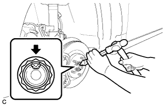
Using a chisel and hammer, stake the front axle shaft nut.
-
-
INSTALL FRONT WHEEL
- Torque:
- 103 N*m { 1050 kgf*cm, 76 ft.*lbf }
-
INSPECT AND ADJUST FRONT WHEEL ALIGNMENT
Tech Tips
-
INSPECT SPEED SENSOR SIGNAL
Tech Tips