STEERING KNUCKLE REMOVAL

Tech Tips
-
Use the same procedure for the RH side and LH side.
-
The procedure listed below is for the LH side.
-
REMOVE FRONT WHEEL
-
REMOVE FRONT AXLE SHAFT NUT
-
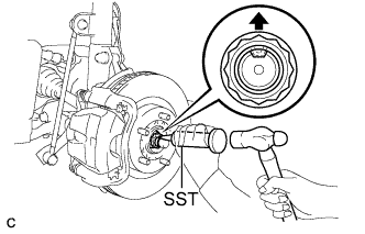
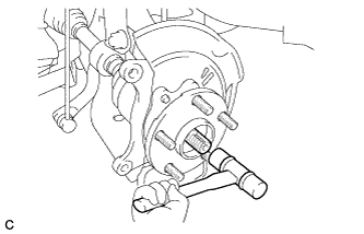
Using SST and a hammer, release the staked part of the front axle shaft nut.
- SST
- 09930-00010
Note
-
Insert SST into the groove with the flat surface facing up.
-
Do not damage the tip of SST using a grinder.
-
Completely unstake the staked part before removing the front axle shaft nut.
-
Do not damage the threads of the drive shaft.
-
Using a socket wrench (30 mm), remove the front axle shaft nut.
-
-
SEPARATE FRONT SPEED SENSOR
-
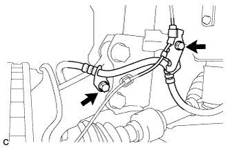
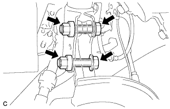
Remove the 2 bolts and separate the front flexible hose and the front speed sensor from the front shock absorber and steering knuckle.
-
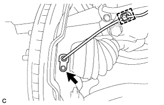
Remove the bolt and clamp to separate the front speed sensor from the steering knuckle.
-
-
SEPARATE TIE ROD END SUB-ASSEMBLY
-
Remove the cotter pin and nut.
-
Install SST to the tie rod end.
- SST
- 09960-20010 ( 09961-02060 )
Note
Make sure that the upper end of the tie rod end and SST are aligned.
-
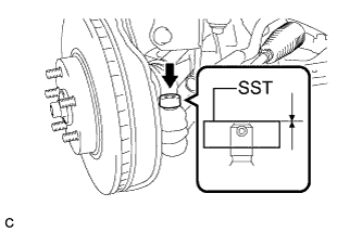
Using SST, separate the tie rod end from the steering knuckle.
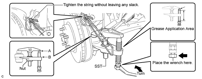
- SST
- 09960-20010 ( 09961-02010 )
CAUTION:
Apply grease to the bolt threads and the tip of SST.
Note
-
Be sure to tighten the string firmly to secure SST to the steering knuckle to prevent SST from falling off.
-
Install SST with the center nut so that A and B shown in the illustration are parallel. Otherwise, the dust cover may be damaged.
-
Be sure to place the wrench on the part indicated in the illustration.
-
Do not damage the front disc brake dust cover.
-
Do not damage the ball joint dust cover.
-
Do not damage the steering knuckle.
-
-
SEPARATE FRONT DISC BRAKE CALIPER ASSEMBLY
-
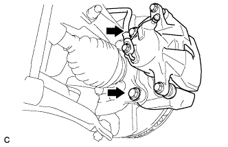
Remove the 2 bolts and separate the front disc brake caliper assembly from the steering knuckle.
Note
Use wire or an equivalent tool to keep the brake caliper from hanging down by the flexible hose.
-
-
REMOVE FRONT DISC
-
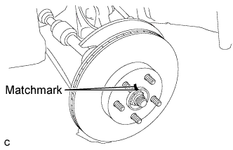
Put matchmarks on the front disc and front axle hub.
Tech Tips
The above step is not necessary when the front disc will be replaced.
-
Remove the front disc.
-
-
SEPARATE FRONT LOWER SUSPENSION ARM SUB-ASSEMBLY
-
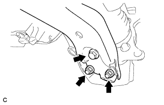
Remove the bolt and 2 nuts, and then pull down the front lower suspension arm sub-assembly to separate the front lower suspension arm sub-assembly from the front lower ball joint.
-
-
REMOVE FRONT AXLE ASSEMBLY
-
Using a plastic hammer, separate the front drive shaft assembly from the front axle assembly.
Tech Tips
If it is difficult to disengage the fitting, tap the end of the drive shaft with a brass bar and a hammer.
-
Remove the 2 bolts and 2 nuts.
-
Remove the front axle assembly from the front drive shaft assembly.
Note
-
Do not deform the dust cover.
-
Do not damage the outboard joint boot.
-
Do not damage the speed sensor rotor.
-
Do not drop the front axle assembly.
-
Use the wire or an equivalent tool to hang the front drive shaft assembly.
-
-
-
REMOVE FRONT LOWER BALL JOINT
-
Secure the front axle hub assembly in a vise using aluminum plates.
-
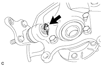
Remove the clip.
-
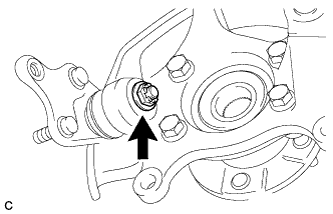
Remove the nut.
-
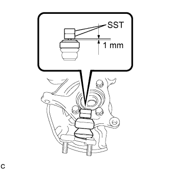
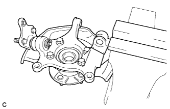
Install 2 spacers (SST spacer B) onto the front lower ball joint assembly as shown in the illustration.
- SST
- 09960-20010 ( 09961-02060, 09961-02060 )
Note
-
To prevent SST from being damaged, make sure that the clearance between the arm and spacers is less than 1 mm (0.0394 in.).
-
Use two of the same SST.
-
Using SST, remove the front lower ball joint assembly as shown in the illustration.
- SST
- 09960-20010 ( 09961-02010 )
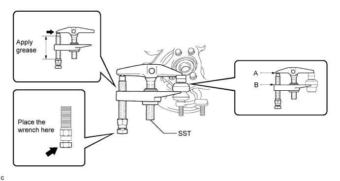
CAUTION:
Apply grease to the threads and end of the SST bolt.
Note
-
Install SST so that A and B are parallel.
-
Be sure to place a wrench on the part indicated in the illustration.
-
Do not damage the front lower ball joint dust cover.
-
-
REMOVE FRONT AXLE HUB SUB-ASSEMBLY
-
Secure the front axle assembly between aluminum plates in a vise.
Note
Do not overtighten the vise.
-
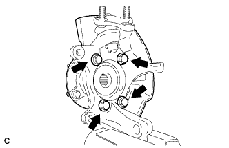
Remove the 4 bolts, front axle hub sub-assembly and dust cover.
Note
Do not drop the front axle hub sub-assembly.
-