FRONT DRIVE SHAFT ASSEMBLY INSTALLATION

-
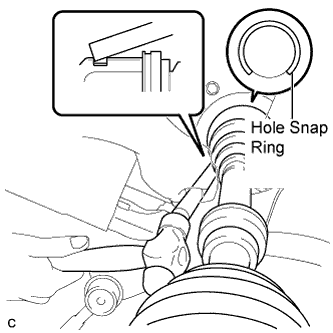
INSTALL FRONT DRIVE SHAFT HOLE SNAP RING LH
-
Install a new front drive shaft hole snap ring LH to the front drive inboard joint assembly LH.
Tech Tips
Face the end gap of the front drive inboard joint hole snap ring downward.
-
-
INSTALL FRONT DRIVE SHAFT ASSEMBLY LH
-
Coat the splines of the inboard joint shaft with MP grease.
-
Align the inboard joint splines, and using a brass bar and a hammer, install the front drive shaft assembly LH.
Note
-
Face the end gap of the front drive shaft hole snap ring LH downward.
-
Do not damage the transaxle case oil seal.
-
Do not damage the inboard joint boot.
-
Make sure to center the front drive shaft assembly LH during installation to prevent damage to the front drive shaft hole snap ring LH
Tech Tips
Confirm whether the drive shaft is securely driven in by checking the reaction force and sound.
-
-
-
INSTALL FRONT DRIVE SHAFT ASSEMBLY RH
-
Align the inboard joint splines, and install the front drive shaft assembly RH with the 2 bolts.
- Torque:
- 64 N*m { 653 kgf*cm, 47 ft.*lbf }
Note
Do not damage the front transaxle case oil seal.
-
-
INSTALL FRONT AXLE ASSEMBLY LH
-
Align the front axle assembly with the splines of the front drive shaft assembly, and then insert the front drive shaft assembly into the front axle assembly.
Note
-
Do not deform the dust cover.
-
Do not damage the outboard joint boot and speed sensor rotor.
-
Make sure to keep the speed sensor rotor and its installation surfaces free of foreign matter.
-
-
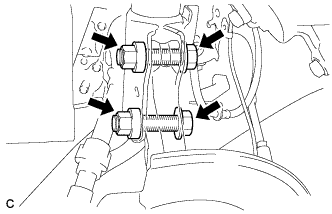
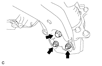
Install the front axle assembly to the front shock absorber with the 2 bolts and 2 nuts as shown in the illustration.
- Torque:
- 240 N*m { 2447 kgf*cm, 177 ft.*lbf }
-
-
INSTALL FRONT AXLE ASSEMBLY RH
Tech Tips
Perform the same procedure as for the LH side Click here.
-
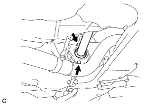
CONNECT FRONT STABILIZER LINK ASSEMBLY LH
-
Install the front stabilizer link assembly LH to the front shock absorber with the nut.
- Torque:
- 74 N*m { 755 kgf*cm, 55 ft.*lbf }
Note
If the ball joint turns together with the nut, use a hexagon wrench (6 mm) to hold the stud bolt.
-
-
CONNECT FRONT STABILIZER LINK ASSEMBLY RH
Tech Tips
Perform the same procedure as for the LH side.
-
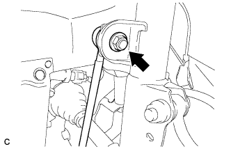
CONNECT FRONT LOWER SUSPENSION ARM SUB-ASSEMBLY LH
-
Connect the front lower suspension arm sub-assembly to the front lower ball joint with the bolt and 2 nuts.
- Torque:
- 93 N*m { 948 kgf*cm, 69 ft.*lbf }
-
-
CONNECT FRONT LOWER SUSPENSION ARM SUB-ASSEMBLY RH
Tech Tips
Perform the same procedure as for the LH side Click here.
-
INSTALL FRONT DISC (for LH Side)
-
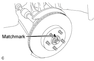
Align the matchmarks of the disc and axle hub, and install the disc.
Note
When installing a new disc, select the installation position where the front disc has minimal runout.
-
-
INSTALL FRONT DISC (for RH Side)
Tech Tips
Perform the same procedure as for the LH side Click here.
-
CONNECT FRONT DISC BRAKE CALIPER ASSEMBLY LH
-
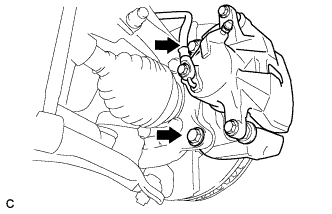
Install the front disc brake caliper assembly to the steering knuckle with the 2 bolts.
- Torque:
- 98 N*m { 999 kgf*cm, 72 ft.*lbf }
-
-
CONNECT FRONT DISC BRAKE CALIPER ASSEMBLY RH
Tech Tips
Perform the same procedure as for the LH side Click here.
-
CONNECT TIE ROD END SUB-ASSEMBLY LH
-
Connect the tie rod end sub-assembly LH to the steering knuckle with the nut.
- Torque:
- 49 N*m { 500 kgf*cm, 36 ft.*lbf }
Note
Further tighten the nut up to 60° if the holes for the cotter pin are not aligned.
-
Install a new cotter pin.
-
-
CONNECT TIE ROD END SUB-ASSEMBLY RH
Tech Tips
Perform the same procedure as for the LH side Click here.
-
CONNECT FRONT SPEED SENSOR LH
-
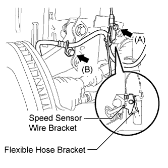
Connect the flexible hose bracket and speed sensor wire bracket with the bolt (A).
- Torque:
- 19 N*m { 194 kgf*cm, 14 ft.*lbf }
Note
Connect the flexible hose bracket first.
-
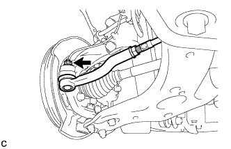
Connect the flexible hose to the steering knuckle with the bolt (B).
- Torque:
- 19 N*m { 194 kgf*cm, 14 ft.*lbf }
-
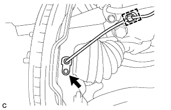
Install the front speed sensor to the steering knuckle with the bolt and clamp.
- Torque:
- 8.5 N*m { 87 kgf*cm, 75 in.*lbf }
Note
-
Do not damage the tip of the speed sensor.
-
Make sure that the speed sensor is free of foreign matter.
-
Do not twist the speed sensor wire.
-
-
CONNECT FRONT SPEED SENSOR RH
Tech Tips
Perform the same procedure as for the LH side Click here.
-
INSTALL FRONT AXLE SHAFT NUT LH
-
Clean the threaded parts on the front drive shaft assembly and new front axle shaft nut using a non-residue solvent.
Note
-
Be sure to perform this work for a new drive shaft.
-
Keep the threaded parts free of oil and foreign matter.
-
-
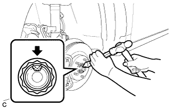
Using a socket wrench (30 mm), while applying the brakes, install the front axle shaft nut.
- Torque:
- for 2GR-FE
- 292 N*m { 2978 kgf*cm, 215 ft.*lbf }
- for 2AZ-FE
- 216 N*m { 2203 kgf*cm, 159 ft.*lbf }
Tech Tips
Tighten the axle shaft nut while the brakes are applied to prevent the front axle from rotating.
-
Using a chisel and hammer, stake the front axle shaft nut.
-
-
INSTALL FRONT AXLE SHAFT NUT RH
Tech Tips
Perform the same procedure as for the LH side Click here.
-
ADD AUTOMATIC TRANSAXLE FLUID (for Automatic Transaxle)
-
ADD CONTINUOUSLY VARIABLE TRANSAXLE FLUID (for CVT)
Tech Tips
-
INSPECT TRANSAXLE FLUID LEVEL
Tech Tips
for U241E: Click here
-
INSPECT FOR FLUID LEAK
-
INSTALL FRONT WHEELS
- Torque:
- 103 N*m { 1050 kgf*cm, 76 ft.*lbf }
-
INSPECT AND ADJUST FRONT WHEEL ALIGNMENT
Tech Tips
-
INSPECT SPEED SENSOR SIGNAL
Tech Tips