FRONT DRIVE SHAFT ASSEMBLY REASSEMBLY

-
INSTALL FRONT DRIVE SHAFT BEARING (for RH Side)
-
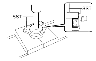
Using SST and a press, install a new front drive shaft bearing to the drive shaft bearing case sub-assembly.
- SST
- 09950-60020 ( 09951-00710 )
- 09950-70010 ( 09951-07100 )
-
-
INSTALL DRIVE SHAFT BEARING CASE SUB-ASSEMBLY (for RH Side)
-
Hold the drive shaft bearing case sub-assembly in a vise between aluminum plates.
Note
Do not overtighten the vise.
-
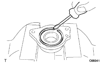
Using a screwdriver, install a new bearing case snap ring to the drive shaft bearing case sub-assembly as shown in the illustration.
-
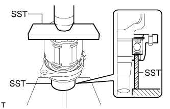
Using SST and a press, install the drive shaft bearing case sub-assembly to the front drive inboard joint assembly RH as shown in the illustration.
- SST
- 09527-10011
- 09710-04081
-
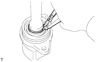
Using a snap ring expander, install a new snap ring as shown in the illustration.
-
-
INSTALL FRONT DRIVE SHAFT DUST COVER (for RH Side)
-
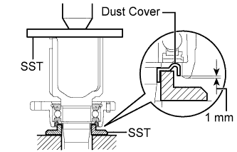
Using SST and a press, install a new front drive shaft dust cover as shown in the illustration.
- SST
- 09527-10011
- 09726-40010
Standard fitting depth 1 mm (0.0394 in.) Note
-
Install the front drive shaft dust cover in the correct direction.
-
Do not press the front drive shaft dust cover in excessively.
-
-
INSTALL FRONT DRIVE SHAFT DUST COVER RH
-
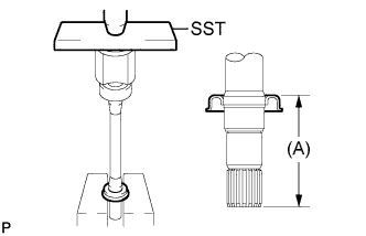
Using SST and a press, install a new front drive shaft dust cover RH as shown in the illustration.
- SST
- 09527-10011
Dimension (A) 2AZ-FE 2GR-FE 91.0 to 92.0 mm (3.59 to 3.62 in.) 110.0 to 111.0 mm (4.34 to 4.37 in.) Note
-
The front drive shaft dust cover RH should be completely installed.
-
Do not damage the front drive shaft dust cover RH.
-
-
INSTALL FRONT DRIVE SHAFT DUST COVER LH
-
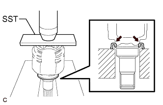
Using SST and a press, install a new front drive shaft dust cover LH into the front drive inboard joint assembly LH until it is flush with the end.
- SST
- 09527-10011
Note
-
Install the front drive shaft dust cover LH in the correct direction.
-
Do not damage the front drive shaft dust cover LH.
-
-
INSTALL OUTBOARD JOINT BOOT (for LH Side)
-
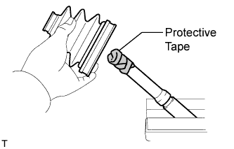
Wrap the splines of the front axle outboard joint shaft assembly LH with protective tape to prevent the boot from being damaged.
-
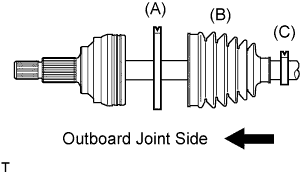
Install new parts onto the front axle outboard joint shaft assembly LH in the following order:
-
No. 2 front axle outboard joint boot clamp LH (A)
-
Outboard joint boot (B)
-
Front axle outboard joint boot clamp LH (C)
-
-
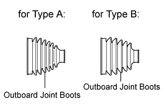
Pack the joint portion of the front axle outboard joint shaft assembly LH and outboard joint boot with grease.
Standard Grease Capacity 2AZ-FE 2GR-FE for Type A 166 to 181 g (5.86 to 6.38 oz.) 205 to 215 g (7.24 to 7.58 oz.) for Type B 171 to 181 g (6.04 to 6.38 oz.) -
Install the outboard joint boot onto the front axle outboard joint shaft assembly LH groove.
Note
-
Do not allow grease to adhere to the boot clamp track of the outboard joint boot.
-
Keep the inside of the outboard joint boot free of foreign matter.
-
-
-
INSTALL OUTBOARD JOINT BOOT (for RH Side)
Tech Tips
Perform the same procedure as for the LH side.
-
INSTALL NO. 2 FRONT AXLE OUTBOARD JOINT BOOT CLAMP LH
CAUTION:
Wear protective gloves. Sharp areas on the parts may injure your hands.
-
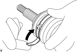
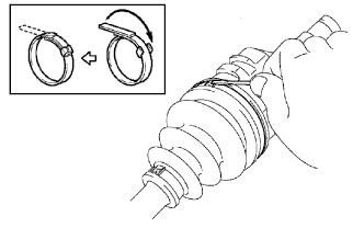
Install the No. 2 front axle outboard joint boot clamp LH onto the outboard joint boot and temporarily fold back the lever.
Note
-
Set the lever into the guide groove correctly and install the clamp as far into the inside of the vehicle as possible.
-
Check the band and the lever for any deformation before folding back the lever.
-
-
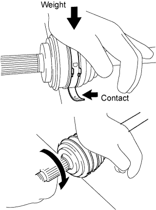
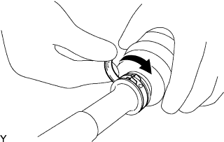
Lean your weight on your hand and roll the outboard joint forward while pressing the outboard joint against the work surface. Roll the outboard joint and fold the lever until a click sound can be heard.
Note
-
Do not damage the deflector.
-
Make sure that the outboard joint is in direct contact with the work surface.
-
-
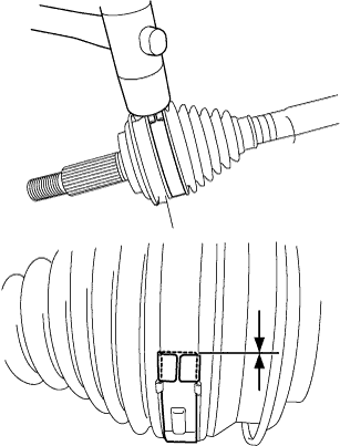
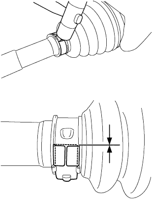
Using a plastic hammer, tap the buckle to secure it while adjusting the clearance between the lever and the groove to make the clearance between the buckle edge and the lever end even.
Note
-
Do not use too much force when tapping with the plastic hammer.
-
Do not damage the outboard joint boot.
-
-
-
INSTALL NO. 2 FRONT AXLE OUTBOARD JOINT BOOT CLAMP RH
Tech Tips
Perform the same procedure as for the LH side.
-
INSTALL FRONT AXLE OUTBOARD JOINT BOOT CLAMP LH
CAUTION:
Wear protective gloves. Sharp areas on the parts may injure your hands.
-
Install the front axle outboard joint boot clamp LH onto the outboard joint boot and temporarily fold back the lever.
Note
-
Set the lever into the guide groove correctly.
-
Check the band and the lever for any deformation before folding back the lever.
-
-
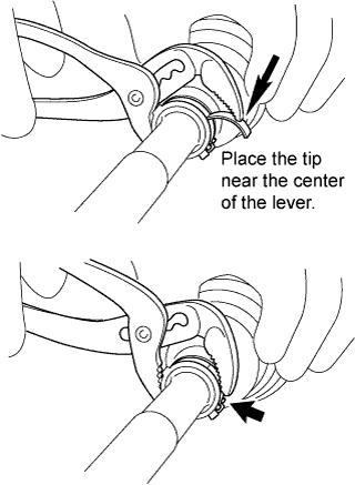
Using water pump pliers, pinch the front axle outboard joint boot clamp LH to temporarily secure it.
-
Using a plastic hammer, tap the buckle to secure it while adjusting the clearance between the lever and the groove to make the clearance between the buckle edge and the lever end even.
Note
-
Do not use too much force when tapping with the plastic hammer.
-
Do not damage the outboard joint boot.
-
-
-
INSTALL FRONT AXLE OUTBOARD JOINT BOOT CLAMP RH
Tech Tips
Perform the same procedure as for the LH side.
-
INSTALL FRONT DRIVE SHAFT DAMPER LH
-
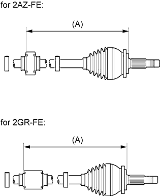
Temporarily install the front drive shaft damper LH and 2 new front drive shaft damper clamps LH to the front axle outboard joint shaft assembly LH as shown in the illustration.
Dimension (A) for 2AZ-FE 199 to 203 mm (7.84 to 7.99 in.) for 2RG-FE 212.5 to 216.5 mm (8.37 to 8.52 in.)
-
-
INSTALL FRONT DRIVE SHAFT DAMPER CLAMP LH
-
Hold the front axle outboard joint shaft assembly LH in a vise between aluminum plates.
Note
Do not overtighten the vise.
-
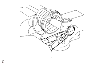
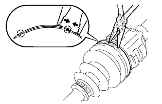
Using needle-nose pliers, engage the 2 claws to install the 2 front drive shaft damper clamps LH as shown in the illustration.
-
-
INSTALL FRONT DRIVE INBOARD JOINT ASSEMBLY LH
-
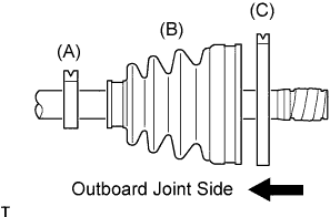
Install new parts onto the front axle outboard joint shaft assembly LH in the following order:
-
Front axle inboard joint boot clamp LH (A)
-
Inboard joint boot (B)
-
No. 2 front axle inboard joint boot clamp LH (C)
-
-
Hold the front axle outboard joint shaft assembly LH in a vise between aluminum plates.
Note
Do not overtighten the vise.
-
Remove the protective tape.
-
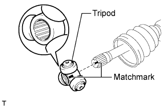
Align the matchmarks and install the tripod to the front axle outboard joint shaft assembly LH as shown in the illustration.
Note
Face the serrated side of the tripod outward and install it to the outboard joint end.
-
Using a brass bar and a hammer, install the tripod to the front axle outboard joint shaft assembly LH.
Note
-
Do not tap the rollers.
-
Keep the tripod free of foreign matter.
-
-
Using a snap ring expander, install a new shaft snap ring to the front axle outboard joint shaft assembly LH.
-
Pack the front drive inboard joint assembly LH and inboard joint boot with grease.
Standard grease capacity 175 to 185 g (6.18 to 6.52 oz.) -
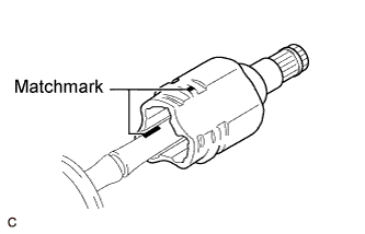
Align the matchmarks and install the front drive inboard joint assembly LH to the front axle outboard joint shaft assembly LH.
-
-
INSTALL FRONT DRIVE INBOARD JOINT ASSEMBLY RH
Tech Tips
Perform the same procedure as for the LH side.
-
INSTALL INBOARD JOINT BOOT
-
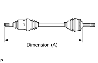
Install the inboard joint boot into the grooves of the front drive inboard joint assembly LH and front axle outboard joint shaft assembly LH.
Dimension (A) Item LH Side RH Side 2AZ-FE 580.2 to 590.2 mm (1.91 to 1.93 ft.) 897.0 to 907.0 mm (2.95 to 2.97 ft.) 2GR-FE 572.6 to 582.6 mm (1.88 to 1.91 ft.) 909.4 to 919.4 mm (2.99 to 3.01 ft.) Note
Keep the grooves free of grease.
-
-
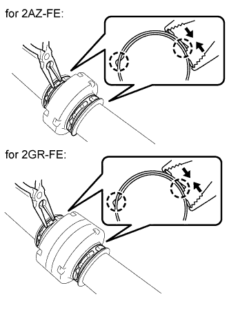
INSTALL FRONT AXLE INBOARD JOINT BOOT CLAMP LH
-
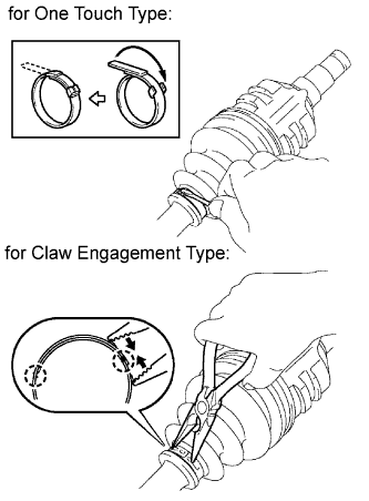
for One Touch Type:
-
Install the front axle inboard joint boot clamp LH to the inboard joint boot.
-
Using a screwdriver, install the front axle inboard joint boot clamp LH as shown in the illustration.
Note
Do not damage the inboard joint boot.
-
-
for Claw Engagement Type:
-
Set the front axle inboard joint boot clamp LH to the inboard joint boot.
-
Using needle-nose pliers, engage the 2 claws to install the front axle inboard joint boot clamp LH as shown in the illustration.
Note
-
Do not damage the inboard joint boot.
-
Do not deform the claw.
-
-
-
-
INSTALL FRONT AXLE INBOARD JOINT BOOT CLAMP RH
Tech Tips
Perform the same procedure as for the LH side.
-
INSTALL NO. 2 FRONT AXLE INBOARD JOINT BOOT CLAMP LH
-
for One Touch Type:
-
Install the No. 2 front axle inboard joint boot clamp LH to the inboard joint boot.
-
Using a screwdriver, install the No. 2 front axle inboard joint boot clamp LH as shown in the illustration.
Note
Do not damage the inboard joint boot.
-
-
for Claw Engagement Type:
-
Set the No. 2 front axle inboard joint boot clamp LH to the inboard joint boot.
-
Using needle-nose pliers, engage the 2 claws to install the No. 2 front axle inboard joint boot clamp LH as shown in the illustration.
Note
-
Do not damage the inboard joint boot.
-
Do not deform the claw.
-
-
-
-
INSTALL NO. 2 FRONT AXLE INBOARD JOINT BOOT CLAMP RH
Tech Tips
Perform the same procedure as for the LH side.
-
INSPECT FRONT DRIVE SHAFT
-
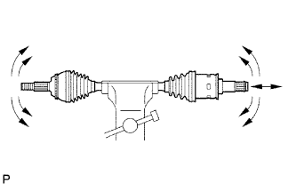
Check that there is no excessive play in the outboard joint.
-
Check that the inboard joint slides smoothly in the thrust direction.
-
Check that there is no excessive play in the radial directions of the inboard joint.
-
Check the boots for damage.
Note
Keep the drive shaft assembly level during inspection.
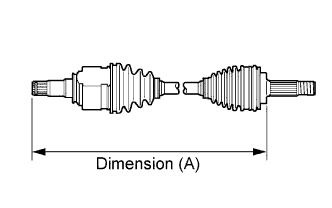
Tech Tips
For dimension (A), refer to the following values.
Dimension (A) Item LH Side RH Side 2AZ-FE 580.2 to 590.2 mm (1.91 to 1.93 ft.) 897.0 to 907.0 mm (2.95 to 2.97 ft.) 2GR-FE 572.6 to 582.6 mm (1.88 to 1.91 ft.) 909.4 to 919.4 mm (2.99 to 3.01 ft.)
-