REAR WHEEL ALIGNMENT INSPECTION

Note
For vehicles equipped with VSC, if the wheel alignment has been adjusted, and if suspension or underbody components have been removed/installed or replaced, be sure to perform the following initialization procedure in order for the system to function normally:
-
Disconnect the cable from the negative (-) battery terminal for more than 2 seconds.
-
Reconnect the cable from the negative (-) battery terminal.
-
INSPECT TIRES
Tech Tips
-
MEASURE VEHICLE HEIGHT
Note
-
Before inspecting the wheel alignment, adjust the vehicle height to the specified value.
-
Be sure to perform measurement on a level surface.
-
If it is necessary to go under the vehicle for measurement, confirm that the parking brake is applied and the vehicle is secured with chocks.
-
Bounce the vehicle up and down at the corners to stabilize the suspension.
-
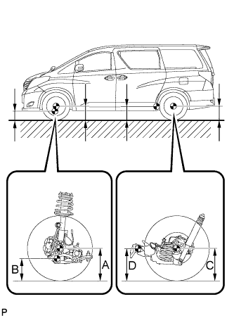
Measure the vehicle height.
Measurement points A Ground clearance of front wheel center B Ground clearance of No. 1 lower suspension arm bushing set bolt center C Ground clearance of rear wheel center D Ground clearance of rear trailing arm bushing set bolt center Vehicle Height (Unloaded Vehicle) Front A - B Rear C - D 93 mm (3.66 in.) -40 mm (1.57 in.)
-
-
INSPECT CAMBER
-
Install the camber-caster-kingpin gauge or place the vehicle on the wheel alignment tester.
-
Inspect the camber.
Camber (Unloaded Vehicle) Camber Inclination Right-left Difference -1°30' +/- 45'
(-1.50° +/- 0.75°)
30' (0.5°) or less Tech Tips
Camber is not adjustable. If the measurement is not within the specified range, inspect the suspension parts for damage and/or wear, and replace them if necessary.
-
-
INSPECT TOE-IN
-
Bounce the vehicle up and down at the corners to stabilize the suspension.
-
Release the parking brake and move the shift lever to N.
-
Push the vehicle straight ahead approximately 5 m (16.4 ft.). (Step A)
-
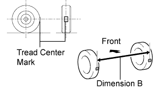
Put tread center marks on the rearmost points of the rear wheels and measure the distance between the marks (dimension B).
-
Slowly push the vehicle straight ahead to cause the rear wheels to rotate 180° using the rear tire valve as a reference point.
Tech Tips
Do not allow the wheels to rotate more than 180°. If the wheels rotate more than 180°, perform the procedure from Step A again.
-
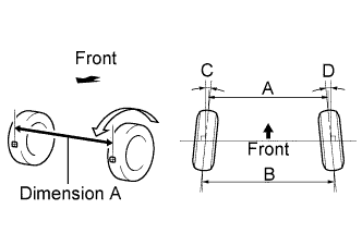
Measure the distance between the tread center marks on the front side of the wheels (dimension A).
Toe-in (Unloaded Vehicle) Item Specified Condition Toe-in
(total)
C + D: 0°14' +/- 18' ( 0.24° +/- 0.30°)
B - A: 3 +/- 4 mm (0.118 +/- 0.157 in.)
Tech Tips
-
Measure "B - A" only when "C + D" cannot be measured.
-
If the toe-in is not within the specified range, inspect the suspension parts and replace them if necessary.
-
-