AUTOMATIC TRANSAXLE ASSEMBLY INSTALLATION

-
INSPECT TORQUE CONVERTER CLUTCH ASSEMBLY
-
Inspect the one-way clutch.
-
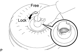
Press on the serrations of the starter with a finger and rotate it. Check that it rotates smoothly when turned clockwise and locks up when turned counterclockwise.
If necessary, clean the converter and recheck the one-way clutch.
Replace the converter if the one-way clutch still fails the check.
-
-
Determine the condition of the torque converter clutch assembly.
-
Check that the following conditions are met:
-
During the stall test or when the shift lever is in N, metallic sounds are not emitted from the torque converter clutch.
-
The one-way clutch turns clockwise and locks when turned counterclockwise.
-
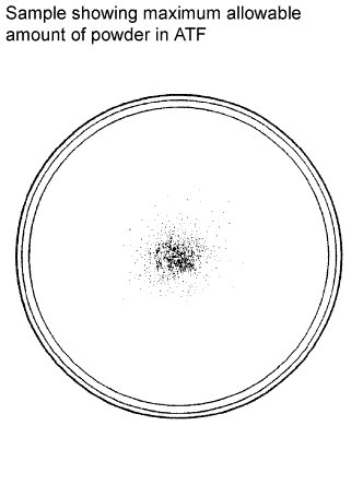
The amount of powder in the ATF is not greater than the sample shown in the illustration.
If the results are not as specified, replace the torque converter clutch assembly.
Tech Tips
The sample illustration shows approximately 0.25 liters (0.26 US qts, 0.22 Imp. qts) of ATF taken from a removed torque converter.
-
-
-
Replace the ATF in the torque converter clutch.
-
If the ATF is discolored and/or has foul odor, stir the ATF in the torque converter clutch thoroughly and drain it.
-
-
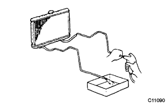
Clean and check the oil cooler and oil pipe line.
-
If the torque converter clutch is inspected or the ATF is replaced, clean the oil cooler and oil pipe line.
Tech Tips
-
Apply compressed air of 196 kPa (2.0 kgf/ cm2, 28 psi) into the inlet hose.
-
If a large amount of powder is found in the ATF, add new ATF using a bucket pump and clean the oil cooler and oil pipe line again.
-
-
If the ATF is cloudy, inspect the oil cooler (radiator).
-
-
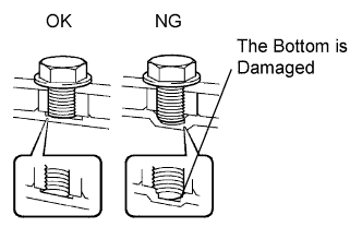
Avoid damaging the torque converter clutch and the oil pump gear.
-
When any marks due to interference are found on the end of a bolt for the torque converter clutch or on the bottom of a bolt hole, replace the bolt and torque converter clutch.
-
All of the bolts should be the same length.
-
Make sure that no spring washers are missing.
-
-
-
INSTALL TORQUE CONVERTER CLUTCH ASSEMBLY
-
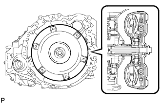
Engage the splines of the input shaft and turbine runner.
-
Engage the splines of the stator shaft and the stator while turning the torque converter clutch assembly.
Tech Tips
If the stator shaft splines are difficult to engage with the stator splines, move the torque converter back approximately 10 mm and engage the splines while rotating the torque converter.
-
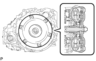
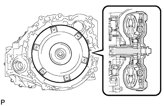
Turn the torque converter clutch assembly to engage the key of the oil pump drive gear into the slot on the torque converter clutch assembly.
-
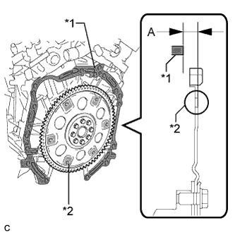
Using a vernier caliper and a straightedge, measure dimension "A" between the transaxle fitting surface of the engine *1 and the converter fitting surface of the drive plate *2. (#)
-
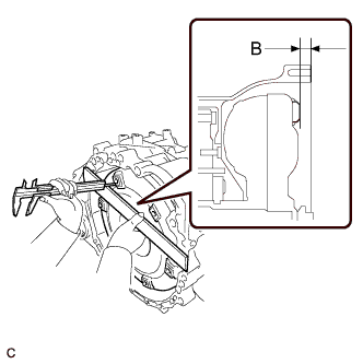
Using a vernier caliper and a straightedge, measure dimension "B" shown in the illustration and check that "B" is greater than "A" (measured in step (#)).
Standard A + 1 mm (0.0394 in.) or more Note
-
Make sure to deduct the thickness of the straightedge.
-
If the transaxle is installed to the engine with the torque converter not sufficiently inserted, the torque converter may be damaged.
Tech Tips
In the case of where a U660E is used with a 2GR-FE, the standard installation depth is 14 mm (0.551 in.) or more.
-
-
-
INSTALL SPEEDOMETER DRIVEN HOLE (ATM) COVER SUB-ASSEMBLY
-
Apply ATF to a new O-ring and install it to the speedometer driven hole (ATM) cover sub-assembly.
-
Install the speedometer driven hole (ATM) cover sub-assembly to the automatic transaxle assembly with the bolt.
- Torque:
- 5.5 N*m { 56 kgf*cm, 49 in.*lbf }
-
-
INSTALL NO. 1 TRANSMISSION CONTROL CABLE BRACKET
-
Install the No. 1 transmission control cable bracket to the automatic transaxle assembly with the 2 bolts.
- Torque:
- 12 N*m { 122 kgf*cm, 9 ft.*lbf }
-
-
INSTALL ENGINE MOUNTING BRACKET LH
-
Install the engine mounting bracket LH to the automatic transaxle assembly with the 4 bolts.
- Torque:
- 64 N*m { 653 kgf*cm, 47 ft.*lbf }
-
-
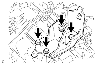
INSTALL WIRE HARNESS CLAMP BRACKET
-
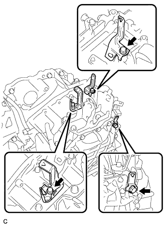
Install the 3 wire harness clamp brackets to the automatic transaxle assembly with the 3 bolts.
-
-
INSTALL AUTOMATIC TRANSAXLE ASSEMBLY
Note
Confirm that 2 knock pins are on the transaxle contact surface of the engine cylinder block before transaxle installation.
-
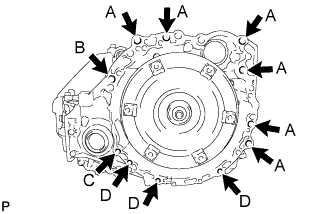
Keeping the engine and automatic transaxle assembly in a horizontal position, align the knock pins with each hole on the automatic transaxle assembly and tighten the 11 bolts shown in the illustration.
- Torque:
- Bolt A
- 64 N*m { 653 kgf*cm, 47 ft.*lbf }
- Bolt B
- 64 N*m { 653 kgf*cm, 47 ft.*lbf }
- Bolt C
- 46 N*m { 469 kgf*cm, 34 ft.*lbf }
- Bolt D
- 43 N*m { 439 kgf*cm, 32 ft.*lbf }
Note
-
Do not forcibly pry on the automatic transaxle assembly.
-
Check that the torque converter rotates.
Tech Tips
Bolt length:
-
Bolt A: 55 mm (2.17 in.)
-
Bolt B: 50 mm (1.97 in.)
-
Bolt C: 41 mm (1.61 in.)
-
Bolt D: 33 mm (1.30 in.)
-
-
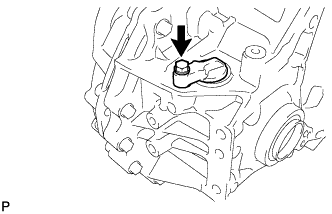
INSTALL TRANSMISSION BREATHER SKIRT
-
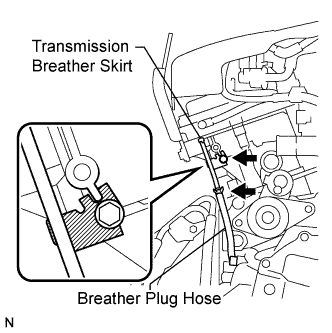
Install the transmission breather skirt to the engine cylinder head with the bolt.
- Torque:
- 5.5 N*m { 56 kgf*cm, 49 in.*lbf }
-
Install the breather plug hose to the transmission breather skirt with the clip.
-
-
INSTALL WIRE HARNESS
-
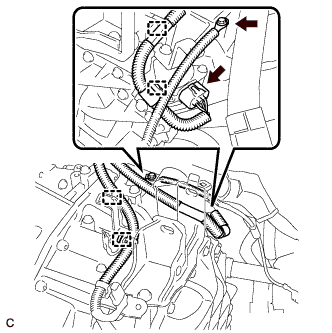
Connect the 4 wire harness clamps and park/neutral position switch connector.
-
Install the ground cable with the bolt.
-
-
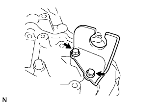
INSTALL TCM
-
Install the TCM to the transaxle.
-
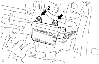
Install and tighten the 2 bolts in the order shown in the illustration.
- Torque:
- 11 N*m { 112 kgf*cm, 8 ft.*lbf }
-
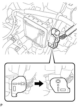
Connect the connector to the TCM.
-
Turn the lock lever and secure the connector with the lock lever.
-
-
INSTALL STARTER ASSEMBLY
-
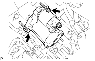
Install the starter with the 2 bolts.
- Torque:
- 37 N*m { 377 kgf*cm, 27 ft.*lbf }
-
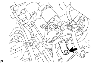
Install the wire harness clamp bracket with the bolt.
-
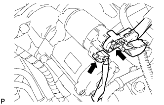
Connect the starter connector.
-
Install the terminal nut and cover the nut with the cap.
- Torque:
- 9.8 N*m { 100 kgf*cm, 87 in.*lbf }
-
-
INSTALL REAR ENGINE MOUNTING BRACKET
-
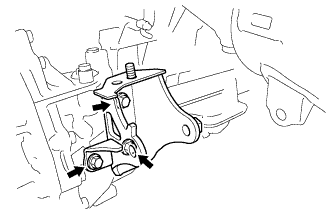
Install the rear engine mounting bracket with the 3 bolts.
- Torque:
- 45 N*m { 459 kgf*cm, 33 ft.*lbf }
-
-
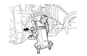
INSTALL FRONT ENGINE MOUNTING BRACKET
-
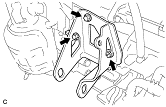
Install the front engine mounting bracket with the 3 bolts.
- Torque:
- 64 N*m { 653 kgf*cm, 47 ft.*lbf }
-
-
INSTALL MANIFOLD STAY
-
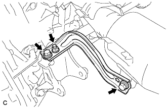
Install the manifold stay with the 2 bolts and nut.
- Torque:
- 34 N*m { 347 kgf*cm, 25 ft.*lbf }
-
-
TEMPORARILY INSTALL FRONT ENGINE MOUNTING INSULATOR
-
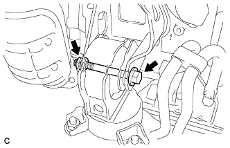
Temporarily install the front engine mounting insulator with the nut and through bolt.
-
-
TEMPORARILY INSTALL REAR ENGINE MOUNTING INSULATOR
-
Temporarily install the rear engine mounting insulator with the through bolt.
-
-
INSTALL ENGINE ASSEMBLY WITH TRANSAXLE
-
CHECK AUTOMATIC TRANSAXLE SYSTEM
Note
If automatic transmission parts have been replaced, refer to the Parts Replacement Compensation Table to determine if any additional operations are necessary Click here.