DESCRIPTION
When the shift lever is in S and it is moved toward "-" or "+", it is possible to select different shift ranges (1st through 6th ranges).
Moving the shift lever toward "+" increases the shift range by one, and moving the shift lever toward "-" decreases the shift range by one.
INSPECTION PROCEDURE
PROCEDURE
- Click here
CHECK HARNESS AND CONNECTOR (BATTERY - TRANSMISSION CONTROL SWITCH)
-
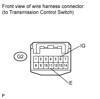
Disconnect the transmission control switch connector of shift lock control unit assembly.
-
Measure the voltage according to the value(s) in the table below.
Standard Voltage Tester Condition Condition Specified Condition G2-6 (IG) - Body ground or other terminals Engine switch on (IG) 11 to 14 V Engine switch off Below 1 V
- OKClick here
- NGClick here
-
- Click here
CHECK HARNESS AND CONNECTOR (TRANSMISSION CONTROL SWITCH - BODY GROUND)
-
Measure the resistance according to the value(s) in the table below.
Standard Resistance Tester Connection Condition Specified Condition G2-11 (E) - Body ground or other terminals Always Below 1 Ω
- OKClick here
- NGClick here
-
- Click here
INSPECT SHIFT LOCK CONTROL UNIT ASSEMBLY (TRANSMISSION CONTROL SWITCH)
-
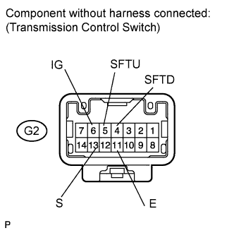
Measure the resistance between each terminal of the transmission control switch when the shift lever is moved to each position.
Standard Resistance Tester Connection Condition Specified Condition 6 (IG) - 13 (S) Shift lever in S, "+" or "-" Below 1 Ω Shift lever not in S, "+" or "-" 10 kΩ or higher 5 (SFTU) - 11 (E) Shift lever held in "+"
(Up-shift)
Below 1 Ω Shift lever not held in "+" 10 kΩ or higher 4 (SFTD) - 11 (E) Shift lever held in "-"
(Down-shift)
Below 1 Ω Shift lever not held in "-" 10 kΩ or higher
- OKClick here
- NGClick here
-
- Click here
CHECK HARNESS AND CONNECTOR (TRANSMISSION CONTROL SWITCH - ECM)
-
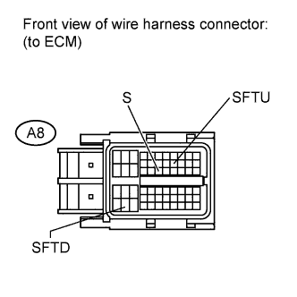
Connect the transmission control switch connector.
-
Disconnect the ECM connector.
-
Turn the engine switch on (IG).
-
Measure the voltage according to the value(s) in the table below.
Standard Voltage Tester Connection Condition Specified Condition A8-25 (S) - Body ground or other terminals
-
Engine switch on (IG)
-
Shift lever in S, "+" or "-"
11 to 14 V A8-25 (S) - Body ground or other terminals
-
Engine switch on (IG)
-
Shift lever not in S, "+" or "-"
Below 1 V -
-
Turn the engine switch off.
-
Disconnect the spiral cable connector.
-
Measure the resistance according to the value(s) in the table below.
Standard Resistance Tester Connection Condition Specified Condition A8-16 (SFTU) - Body ground or other terminals Shift lever held in "+"
(Up-shift)
Below 1 Ω Shift lever not held in "+" 10 kΩ or higher A8-51 (SFTD) - Body ground or other terminals Shift lever held in "-"
(Down-shift)
Below 1 Ω Shift lever not held in "-" 10 kΩ or higher
- OKClick here
- NGClick here
-
- Click here
PROCEED TO NEXT SUSPECTED AREA SHOWN IN PROBLEM SYMPTOMS TABLEClick here
- Click here
REPAIR OR REPLACE HARNESS OR CONNECTOR
- Click here
REPLACE SHIFT LOCK CONTROL UNIT ASSEMBLY (TRANSMISSION CONTROL SWITCH)Click here