VALVE BODY ASSEMBLY INSPECTION

-
INSPECT SHIFT SOLENOID VALVE SL
-
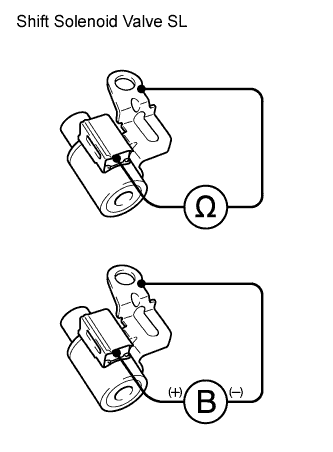
Measure the resistance according to the value(s) in the table below.
Standard Resistance Tester Connection Condition Specified Condition Solenoid Connector (SL) - Solenoid Body (SL) 20°C (68°F) 11 to 15 Ω If the value is not as specified, replace the shift solenoid valve.
-
Connect a positive (+) battery lead to the terminal of the solenoid connector, and a negative (-) battery lead to the solenoid body, and check the operation of the valve.
Note
When using battery voltage during the inspection, do not bring the positive and negative tester probes too close to each other as a short circuit may occur.
OK Valve moves and makes an operating sound. If the operation cannot be done as specified, replace the shift solenoid valve.
-
-
INSPECT SHIFT SOLENOID VALVE SLT
-
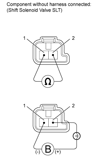
Measure the resistance according to the value(s) in the table below.
Standard Resistance Tester Connection Condition Specified Condition 1 - 2 20°C (68°F) 5.0 to 5.6 Ω If the value is not as specified, replace the shift solenoid valve.
-
Connect a positive (+) battery lead with a 21 W bulb to terminal 2 and a negative (-) battery lead to terminal 1 of the solenoid valve connector, and check the operation of the valve.
Note
When using battery voltage during the inspection, do not bring the positive and negative tester probes too close to each other as a short circuit may occur.
OK Valve moves and makes an operating sound. If the operation cannot be done as specified, replace the shift solenoid valve.
-
-
INSPECT SHIFT SOLENOID VALVE SLU
-

Measure the resistance according to the value(s) in the table below.
Standard Resistance Tester Connection Condition Specified Condition 1 - 2 20°C (68°F) 5.0 to 5.6 Ω If the value is not as specified, replace the shift solenoid valve.
-
Connect a positive (+) battery lead with a 21 W bulb to terminal 2 and a negative (-) battery lead to terminal 1 of the solenoid valve connector, and check the operation of the valve.
Note
When using battery voltage during the inspection, do not bring the positive and negative tester probes too close to each other as a short circuit may occur.
OK Valve moves and makes an operating sound. If the operation cannot be done as specified, replace the shift solenoid valve.
-
-
INSPECT SHIFT SOLENOID VALVE SL1
-
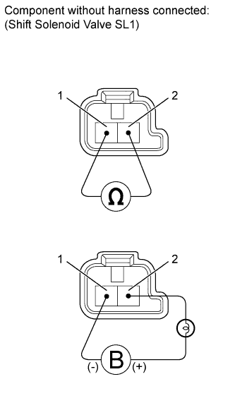
Measure the resistance according to the value(s) in the table below.
Standard Resistance Tester Connection Condition Specified Condition 1 - 2 20°C (68°F) 5.0 to 5.6 Ω If the value is not as specified, replace the shift solenoid valve.
-
Connect a positive (+) battery lead with a 21 W bulb to terminal 2 and a negative (-) battery lead to terminal 1 of the solenoid valve connector, and check the operation of the valve.
Note
When using battery voltage during the inspection, do not bring the positive and negative tester probes too close to each other as a short circuit may occur.
OK Valve moves and makes an operating sound. If the operation cannot be done as specified, replace the shift solenoid valve.
-
-
INSPECT SHIFT SOLENOID VALVE SL2
-

Measure the resistance according to the value(s) in the table below.
Standard Resistance Tester Connection Condition Specified Condition 1 - 2 20°C (68°F) 5.0 to 5.6 Ω If the value is not as specified, replace the shift solenoid valve.
-
Connect a positive (+) battery lead with a 21 W bulb to terminal 2 and a negative (-) battery lead to terminal 1 of the solenoid valve connector, and check the operation of the valve.
Note
When using battery voltage during the inspection, do not bring the positive and negative tester probes too close to each other as a short circuit may occur.
OK Valve moves and makes an operating sound. If the operation cannot be done as specified, replace the shift solenoid valve.
-
-
INSPECT SHIFT SOLENOID VALVE SL3
-

Measure the resistance according to the value(s) in the table below.
Standard Resistance Tester Connection Condition Specified Condition 1 - 2 20°C (68°F) 5.0 to 5.6 Ω If the value is not as specified, replace the shift solenoid valve.
-
Connect a positive (+) battery lead with a 21 W bulb to terminal 2 and a negative (-) battery lead to terminal 1 of the solenoid valve connector, and check the operation of the valve.
Note
When using battery voltage during the inspection, do not bring the positive and negative tester probes too close to each other as a short circuit may occur.
OK Valve moves and makes an operating sound. If the operation cannot be done as specified, replace the shift solenoid valve.
-
-
INSPECT SHIFT SOLENOID VALVE SL4
-
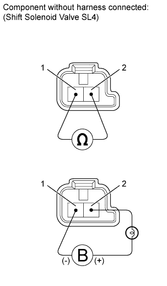
Measure the resistance according to the value(s) in the table below.
Standard Resistance Tester Connection Condition Specified Condition 1 - 2 20°C (68°F) 5.0 to 5.6 Ω If the value is not as specified, replace the shift solenoid valve.
-
Connect a positive (+) battery lead with a 21 W bulb to terminal 2 and a negative (-) battery lead to terminal 1 of the solenoid valve connector, and check the operation of the valve.
Note
When using battery voltage during the inspection, do not bring the positive and negative tester probes too close to each other as a short circuit may occur.
OK Valve moves and makes an operating sound. If the operation cannot be done as specified, replace the shift solenoid valve.
-