AIR COOLED OIL COOLER INSTALLATION

-
INSTALL OIL WITH HOSE COOLER ASSEMBLY
-
Install the transmission oil cooler air duct to the oil cooler assembly with the 4 bolts.
- Torque:
- 4.9 N*m { 50 kgf*cm, 43 in.*lbf }
-
Install the lower oil cooler bracket to the oil cooler assembly with the bolt.
- Torque:
- 5.5 N*m { 56 kgf*cm, 49 in.*lbf }
-
Install the upper oil cooler bracket to the oil cooler assembly with the 2 bolts.
- Torque:
- 5.5 N*m { 56 kgf*cm, 49 in.*lbf }
-
Install the oil with hose cooler assembly with the 3 bolts.
- Torque:
- 19 N*m { 194 kgf*cm, 14 ft.*lbf }
-
-
INSTALL NO. 1 OIL COOLER INLET HOSE
-
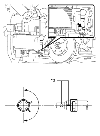
Text in Illustration *a Matchmark Align the matchmarks and install the No. 1 oil cooler inlet hose to the oil with hose cooler assembly.
-
Install the clip within the range shown in the illustration.
-
-
INSTALL NO. 1 OIL COOLER OUTLET HOSE
-
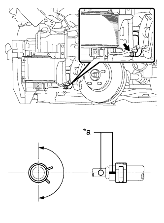
Text in Illustration *a Matchmark Align the matchmarks and install the No. 1 oil cooler outlet hose to the oil with hose cooler assembly.
-
Install the clip within the range shown in the illustration.
-
-
ADD AUTOMATIC TRANSAXLE FLUID
-
INSTALL NO. 3 INTAKE AIR RESONATOR
-
Install the pin and No. 3 intake air resonator to the body.
-
Install the 2 bolts.
- Torque:
- 5.0 N*m { 51 kgf*cm, 44 in.*lbf }
-
Return the front fender splash shield sub-assembly to its original position.
-
-
INSTALL FRONT BUMPER ASSEMBLY (for ALPHARD)
-
INSTALL FRONT BUMPER ASSEMBLY (for VELLFIRE)
-
INSTALL REAR ENGINE UNDER COVER LH
-
INSTALL ENGINE UNDER COVER
-
INSTALL NO. 1 ENGINE UNDER COVER
-
INSTALL FRONT WHEEL LH
- Torque:
- 103 N*m { 1050 kgf*cm, 76 ft.*lbf }