AUTOMATIC TRANSAXLE SYSTEM, Diagnostic DTC:P0705

| DTC Code | DTC Name |
|---|---|
| P0705 | Transmission Range Sensor Circuit Malfunction (PRNDL Input) |
DESCRIPTION
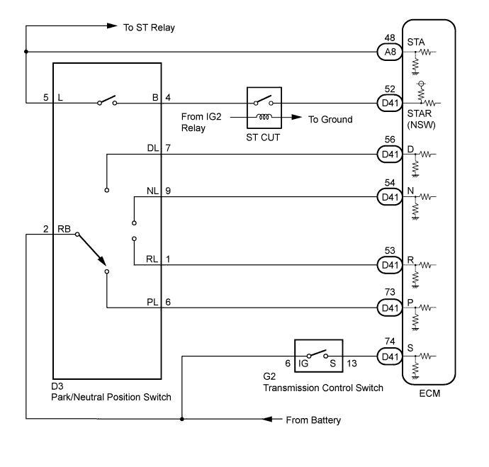
The park/neutral position switch detects the shift lever position and sends signals to the ECM.
| DTC No. | DTC Detection Condition | Trouble Area |
|---|---|---|
| P0705 | (A) Any 2 or more signals of the following are ON simultaneously (2-trip detection logic)
(B) Any 2 or more signals of the following are ON simultaneously (2-trip detection logic)
(C) When any of following conditions is met for 2.0 sec. or more in the S position (2-trip detection logic)
(D) All switches are OFF simultaneously for STAR (NSW), P, N, R, D positions (2-trip detection logic).
|
|
MONITOR DESCRIPTION
These DTCs indicate a problem with the park/neutral position switch and the wire harness in the park/neutral position switch circuit.
The park/neutral position switch detects the shift lever position and sends a signal to the ECM.
For security, the park/neutral position switch detects the shift lever position so that engine can be started only when the shift lever is in the P or N position.
The park/neutral position switch sends a signal to the ECM according to the shift position (P, R, N, or D). The ECM determines that there is a problem with the switch or related parts if it receives more than 1 position signal simultaneously. The ECM will turn on the MIL and store the DTC.
WIRING DIAGRAM
INSPECTION PROCEDURE
PROCEDURE
-
CHECK HARNESS AND CONNECTOR (BATTERY - PARK/NEUTRAL POSITION SWITCH)
-

Disconnect the park/neutral position switch connector.
-
Turn the engine switch on (IG)
-
Measure the voltage according to the value(s) in the table below.
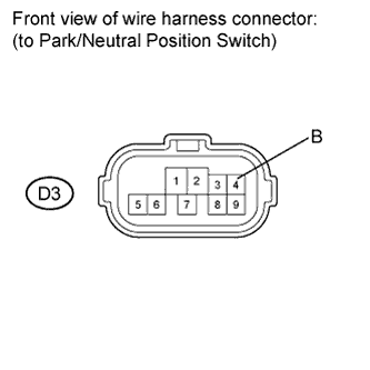
Standard voltage Tester Connection Switch Condition Specified Condition D3-2 (RB) - Body ground Engine switch on (IG) 11 to 14 V
NG 
REPAIR OR REPLACE HARNESS OR CONNECTOR
OK 
-
-
CHECK HARNESS AND CONNECTOR (OUTPUT SIGNAL)
-
Turn the engine switch on (IG).
-
Measure the voltage according to the value(s) in the table below.
Standard voltage Tester Connection Switch Condition Specified Condition D3-4 (B) - Body ground Engine switch on (IG) 11 to 14 V
NG
CHECK CRANKING HOLDING FUNCTION CIRCUIT
OK
-
-
INSPECT PARK/NEUTRAL POSITION SWITCH ASSEMBLY
-
Disconnect the park/neutral position switch connector.
-
Measure resistance according to the value(s) in the table below when the shift lever is moved to each position.
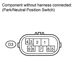
Standard resistance Tester Connection Shift Position Specified Condition 4 - 5 P and N Below 1 Ω Except P and N 10 Ω or higher 2 - 6 P Below 1 Ω Except P 10 Ω or higher 2 - 1 R Below 1 Ω Except R 10 Ω or higher 2 - 9 N Below 1 Ω Except N 10 Ω or higher 2 - 7 D, S, "+" and "-" Below 1 Ω Except D, S, "+" and "-" 10 Ω or higher
NG
REPLACE PARK/NEUTRAL POSITION SWITCH ASSEMBLY Click here
OK
-
-
CHECK HARNESS AND CONNECTOR (PARK/NEUTRAL POSITION SWITCH - ECM)
-
Connect the park/neutral position switch connector.
-
Disconnect the ECM connector.
-
Turn the engine switch on (IG), and measure the voltage according to the value(s) in the table below when the shift lever is moved to each position.
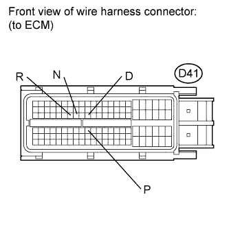
Standard voltage Tester Connection Shift Position Specified Condition D41-73 (P) - Body ground P 11 to 14 V Except P Below 1 V D41-54 (N) - Body ground N 11 to 14 V Except N Below 1 V D41-53 (R) - Body ground R 11 to 14 V*
Except R Below 1 V D41-56 (D) - Body ground D and S 11 to 14 V Except D and S Below 1 V Tech Tips
*: The voltage will drop slightly due to the turning on of the back up light.
NG
REPAIR OR REPLACE HARNESS OR CONNECTOR
OK
-
-
CHECK HARNESS AND CONNECTOR (BATTERY - TRANSMISSION CONTROL SWITCH)
-
Disconnect the transmission control switch connector of shift lock control unit assembly.
-
Turn the engine switch on (IG).
-
Measure the voltage according to the value(s) in the table below.
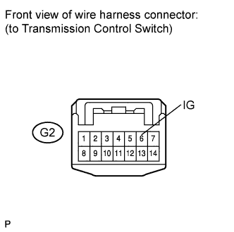
Standard voltage Tester Connection Switch Condition Specified Condition G2-6 (IG) - Body ground Engine switch on (IG) 11 to 14 V
NG
REPAIR OR REPLACE HARNESS OR CONNECTOR
OK
-
-
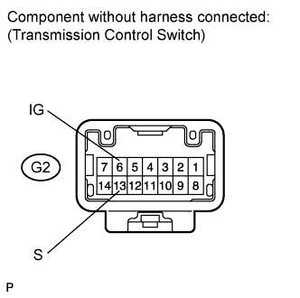
INSPECT SHIFT LOCK CONTROL UNIT (TRANSMISSION CONTROL SWITCH)
-
Disconnect the transmission control switch connector of shift lock control unit assembly.
-
Measure the resistance according to the value(s) in the table below when the shift lever is moved to each position.
Standard resistance Tester Connection Shift Position Specified Condition G2-6 (IG) - G2-13 (S) S, "+" and "-" Below 1 Ω Except S, "+" and "-" 10 Ω or higher
NG
REPLACE SHIFT LOCK CONTROL UNIT Click here
OK
-
-
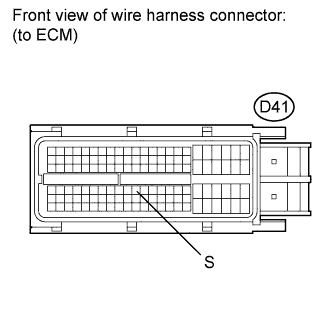
CHECK HARNESS AND CONNECTOR (TRANSMISSION CONTROL SWITCH - ECM)
-
Connect the transmission control switch connector.
-
Disconnect the ECM connector.
-
Turn the engine switch on (IG), and measure the voltage according to the value(s) in the table below when the shift lever is moved to each position.
Standard voltage Tester Connection Shift Position Specified Condition D41-74 (S) - Body ground S, "+" and "-" 11 to 14 V Except S, "+" and "-" Below 1 V
NG
REPAIR OR REPLACE HARNESS OR CONNECTOR
OK 
REPLACE ECM Click here
-