AUTOMATIC TRANSAXLE UNIT DISASSEMBLY

-
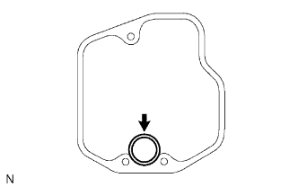
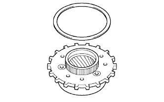
REMOVE SPEEDOMETER DRIVEN HOLE COVER SUB-ASSEMBLY
-
Remove the bolt and speedometer driven hole cover sub-assembly from the transaxle.
-
Remove the O-ring from the speedometer driven hole cover sub-assembly.
-
-
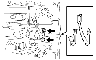
REMOVE PARK/NEUTRAL POSITION SWITCH ASSEMBLY
-
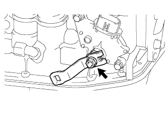
Remove the nut, washer and control shaft lever.
-
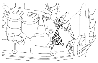
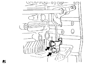
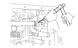
Using a screwdriver, unstake the lock plate and remove the nut and lock plate.
-
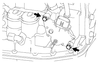
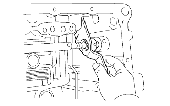
Remove the 2 bolts and pull out the park/neutral position switch assembly.
-
-
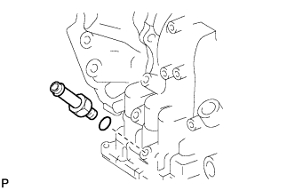
REMOVE BREATHER PLUG SUB-ASSEMBLY
-
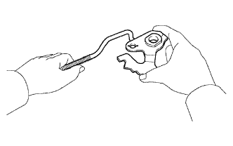
Remove the breather plug sub-assembly from the breather plug hose.
-
-
REMOVE BREATHER PLUG HOSE
-
Remove the breather plug hose from the No. 2 breather plug.
-
-
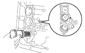
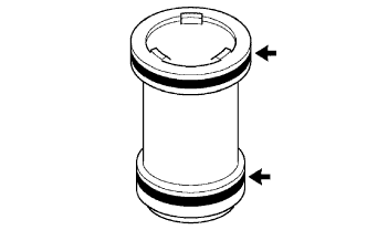
REMOVE NO. 2 BREATHER PLUG
-
Remove the No. 2 breather plug from the transaxle.
-
Remove the O-ring from the No. 2 breather plug.
-
-
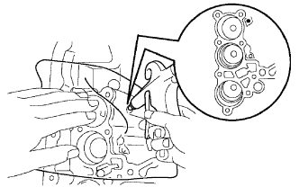
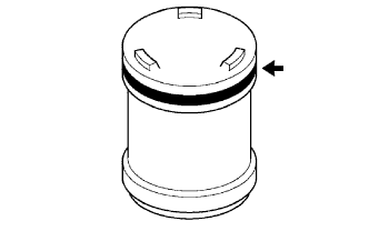
REMOVE OIL COOLER OUTLET TUBE UNION

-
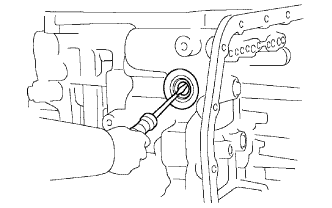
Remove the oil cooler outlet tube union.
-
Remove the O-ring from the oil cooler outlet tube union.
-
-
REMOVE OIL COOLER INLET TUBE UNION
-
Remove the oil cooler inlet tube union.
-
Remove the O-ring from the oil cooler inlet tube union.
-
-
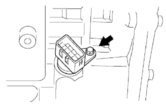
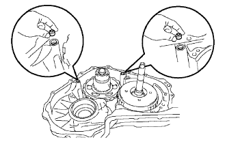
REMOVE SPEED SENSOR
-
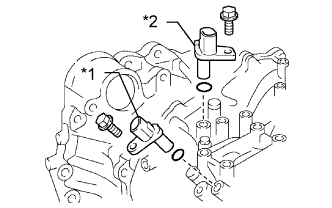
Text in Illustration *1 Speed Sensor NT *2 Speed Sensor NC Remove the speed sensor NT.
-
Remove the bolt and speed sensor.
-
Remove the O-ring from the speed sensor.
-
-
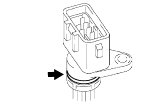
Remove the speed sensor NC.
-
Remove the bolt and speed sensor.
-
Remove the O-ring from the speed sensor.
-
-
-
REMOVE NO. 1 TRANSAXLE CASE PLUG
-
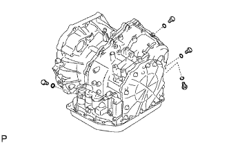
Remove the 4 No. 1 transaxle case plugs from the transaxle.
-
Remove the 4 O-rings from the 4 No. 1 transaxle case plugs.
-
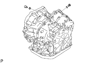
Remove the 2 No. 1 transaxle case plugs.
-
Remove the 2 O-rings from the 2 No. 1 transaxle case plugs.
-
-
SECURE AUTOMATIC TRANSAXLE ASSEMBLY
-
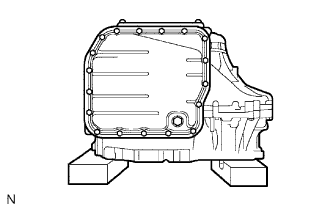
Place the transaxle assembly on wooden blocks.
-
-
REMOVE AUTOMATIC TRANSAXLE OIL PAN SUB-ASSEMBLY
-
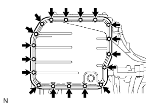
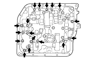
Remove the 18 bolts and automatic transaxle oil pan sub-assembly from the transaxle.
-
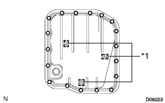
Text in Illustration *1 Magnet Remove the automatic transaxle oil pan sub-assembly and 3 magnets.
-
Remove the gasket from the automatic transaxle oil pan sub-assembly.
-
-
INSPECT AUTOMATIC TRANSAXLE OIL PAN SUB-ASSEMBLY
-
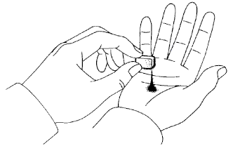
Remove the magnets and use them to collect any steel chips. Look carefully at the chips and particles in the pan and on the magnets to anticipate what type of wear has occurred in the transaxle.
Steel (magnetic): bearing, gear and plate wear
Brass (non-magnetic): bush wear
-
-
REMOVE VALVE BODY OIL STRAINER ASSEMBLY
-
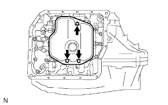
Remove the 3 bolts and valve body oil strainer assembly.
-
Remove the O-ring from the valve body oil strainer assembly.
-
-
REMOVE TRANSMISSION WIRE
-
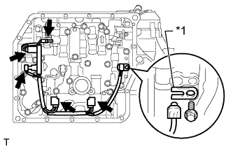
Text in Illustration *1 Lock Plate Disconnect the 5 connectors from the shift solenoid valves.
-
Remove the bolt, lock plate and ATF temperature sensor.
-
Remove the bolt and transmission wire from the transaxle.
-
Remove the O-ring from the transmission wire.
-
-
REMOVE TRANSMISSION VALVE BODY ASSEMBLY
-
Support the transmission valve body assembly and remove the 17 bolts and the transmission valve body assembly.
Note
Be careful not to drop the check valve body, spring and accumulator piston.
-
-
REMOVE NO. 1 GOVERNOR APPLY GASKET
-
Remove the No. 1 governor apply gasket from the transaxle.
-
-
REMOVE TRANSAXLE CASE 2ND BRAKE GASKET
-
Remove the transaxle case 2nd brake gasket from the transaxle.
-
-
REMOVE BRAKE DRUM GASKET
-
Remove the brake drum gasket from the transaxle.
-
-
REMOVE CHECK BALL BODY
-
Remove the check ball body and spring from the transaxle.
-
-
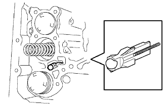
REMOVE C-3 ACCUMULATOR PISTON
-
Remove the spring from the C-3 accumulator piston.
-
Apply compressed air (392 kPa, 4.0 kgf/cm2, 57 psi) to the oil hole and remove the C-3 accumulator piston.
CAUTION:
Applying compressed air may cause the piston to jump out. When removing the piston, hold it with your hand using a piece of cloth.
Note
Do not splash ATF when applying compressed air.
-
Remove the O-ring from the C-3 accumulator piston.
-
-
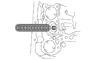
REMOVE C-1 ACCUMULATOR PISTON
-
Apply compressed air (392 kPa, 4.0 kgf/cm2, 57 psi) to the oil hole and remove the C-1 accumulator piston and spring.
CAUTION:
Applying compressed air may cause the piston to jump out. When removing the piston, hold it with your hand using a piece of cloth.
Note
Do not splash ATF when applying compressed air.
-
Remove the 2 O-rings from the C-1 accumulator piston.
-
-
REMOVE B-3 ACCUMULATOR PISTON
-
Apply compressed air (392 kPa, 4.0 kgf/cm2, 57 psi) to the oil hole and remove the B-3 accumulator piston and 2 springs.
CAUTION:
Applying compressed air may cause the piston to jump out. When removing the piston, hold it with your hand using a piece of cloth.
Note
Do not splash ATF when applying compressed air.
-
Remove the O-ring from the B-3 accumulator piston.
-
-
REMOVE MANUAL DETENT SPRING SUB-ASSEMBLY
-
Remove the 2 bolts, manual detent spring sub-assembly and spring cover.
-
-
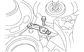
REMOVE PARKING LOCK PAWL BRACKET
-
Remove the 2 bolts and parking lock pawl bracket.
-
-
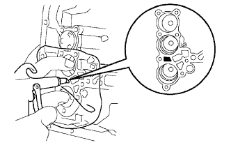
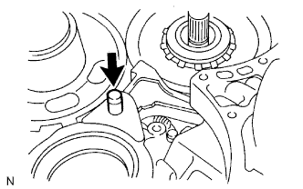
REMOVE MANUAL VALVE LEVER SHAFT RETAINER SPRING
-
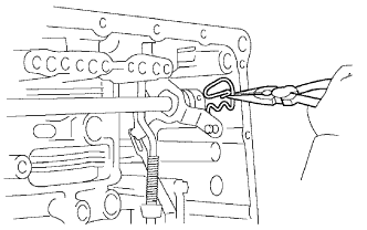
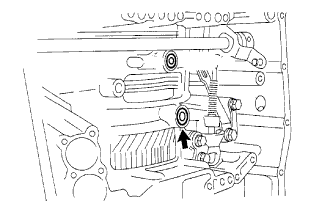
Using needle-nose pliers, remove the manual valve lever shaft retainer spring.
-
-
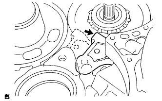
REMOVE MANUAL VALVE LEVER SUB-ASSEMBLY
-
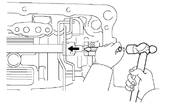
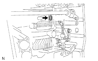
Using a chisel and hammer, unstake and remove the spacer.
-
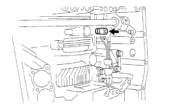
Using a pin punch (3 mm) and hammer, tap out the manual valve lever shaft spring pin.
Tech Tips
Slowly drive out the pin so that it will not fall into the transaxle.
-
Remove the manual valve lever shaft and manual valve lever sub-assembly.
-
-
REMOVE PARKING LOCK ROD SUB-ASSEMBLY
-
Remove the parking lock rod sub-assembly from the manual valve lever sub-assembly.
-
-
REMOVE MANUAL VALVE LEVER SHAFT OIL SEAL
-
Using a screwdriver, pry out the oil seal from the transaxle.
-
-
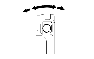
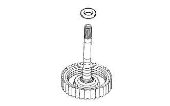
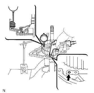
INSPECT INPUT SHAFT END PLAY
-
Secure the transaxle case with the oil pump side facing up.
-
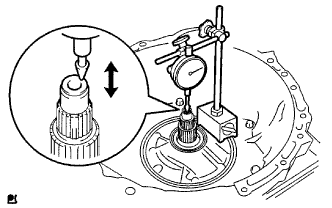
Using a dial indicator, measure the input shaft end play.
Standard end play 0.26 to 1.25 mm (0.0103 to 0.0492 in.) If the end play is not as specified, replace the stator shaft thrust needle roller bearing and the forward clutch hub thrust needle roller bearing.
-
-
REMOVE TRANSAXLE HOUSING
-
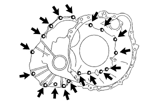
Remove the 18 bolts.
-
Tap on the circumference of the transaxle housing with a plastic-faced hammer to remove the transaxle housing from the transaxle.
Note
The differential may be accidentally removed when the transaxle housing is removed.
-
-
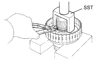
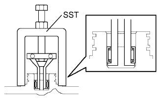
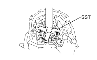
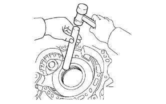
REMOVE UNDERDRIVE CYLINDRICAL ROLLER BEARING
-
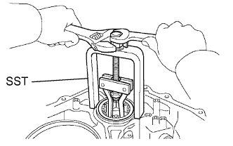
Using SST, remove the underdrive cylindrical roller bearing from the transaxle.
- SST
- 09514-35011
-
-
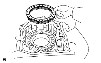
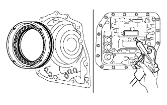
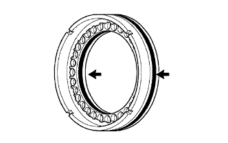
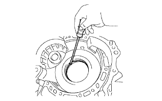
REMOVE UNDERDRIVE OUTPUT SHAFT OIL SEAL RING
-
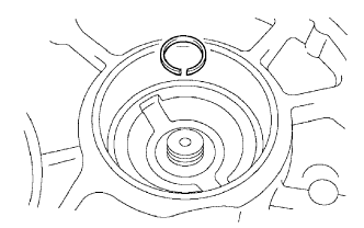
Remove the underdrive output shaft oil seal ring from the transaxle housing.
-
-
REMOVE OIL PUMP ASSEMBLY
-
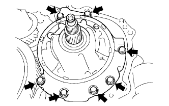
Remove the 7 bolts and oil pump assembly from the transaxle.
-
-
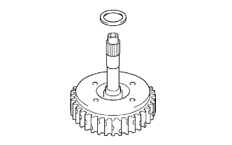
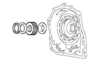
REMOVE THRUST NEEDLE ROLLER BEARING
-
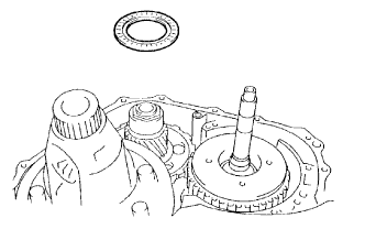
Remove the thrust needle roller bearing from the underdrive planetary gear assembly.
-
-
REMOVE NO. 2 THRUST BEARING UNDERDRIVE RACE
-
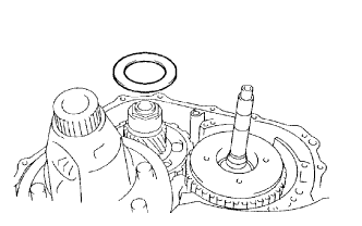
Remove the thrust bearing race from the underdrive planetary gear assembly.
-
-
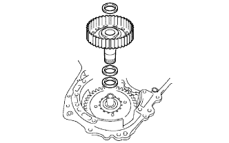
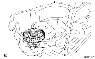
REMOVE FRONT DIFFERENTIAL ASSEMBLY
-
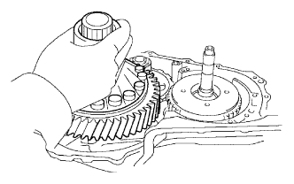
Remove the front differential assembly from the transaxle.
-
-
REMOVE OVERDRIVE BRAKE GASKET
-
Remove the 2 overdrive brake gaskets from the transaxle.
-
-
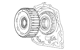
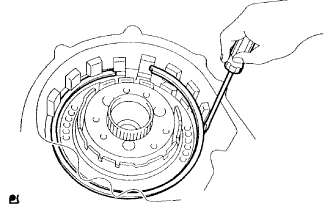
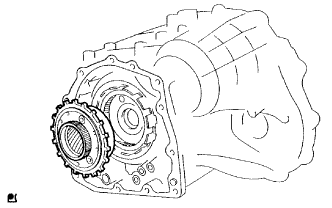
REMOVE FORWARD CLUTCH ASSEMBLY
-
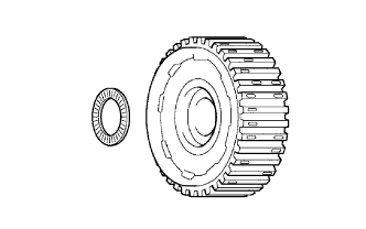
Remove the forward clutch assembly from the transaxle.
-
Remove the thrust bearing from the forward clutch.
-
-
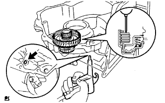
INSPECT PACK CLEARANCE OF FORWARD CLUTCH
-
Install the forward clutch on the oil pump.
Note
Be careful not to damage the oil seal ring of the oil pump.
-
Using a dial indicator, measure the forward clutch piston stroke while applying and releasing compressed air (392 kPa, 4.0 kgf/cm2, 57 psi).
Standard piston stroke 1.74 to 2.08 mm (0.0685 to 0.0819 in.) If the piston stroke is less than the minimum, the parts may have been assembled incorrectly. Check and reassemble again.
If the clearance is not as specified, select another flange.
Tech Tips
There are 5 different thicknesses of flanges.
Standard flange thickness No. Thickness No. Thickness 1 3.00 mm (0.1181 in.) 4 3.45 mm (0.1358 in.) 2 3.15 mm (0.1240 in.) 5 3.60 mm (0.1417 in.) 3 3.30 mm (0.1299 in.) - -
-
-
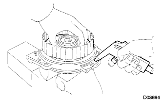
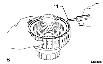
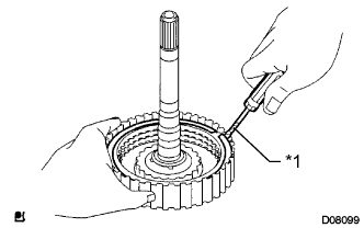
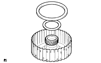
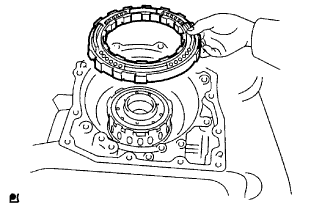
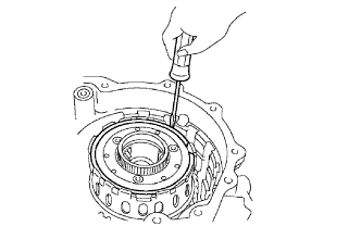
REMOVE FORWARD CLUTCH FLANGE HOLE SNAP RING
-
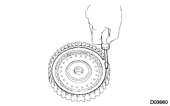
Using a screwdriver, remove the forward clutch flange hole snap ring.
-
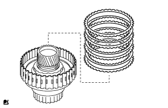
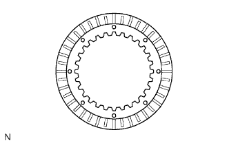
Remove the flange, 5 discs and 5 plates.
-
-
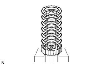
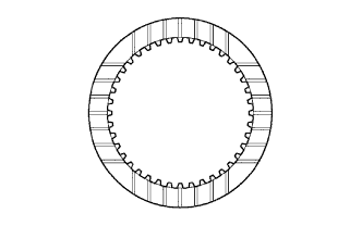
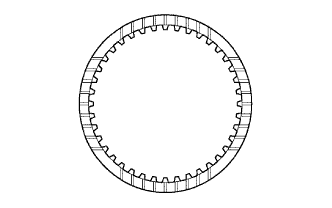
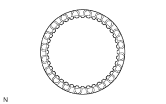
INSPECT FORWARD MULTIPLE DISC CLUTCH DISC
-
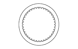
Check to see if the sliding surface of the flange, discs and plates are worn or burnt.
If necessary, replace them.
Tech Tips
-
If the lining of the disc is peeling off or discolored, replace all discs.
-
Before assembling new discs, soak them in ATF for at least 15 minutes.
-
-
-
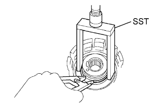
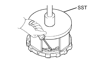
REMOVE FORWARD CLUTCH RETURN SPRING SUB-ASSEMBLY
-
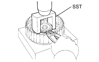
Place SST on the spring retainer of the forward clutch return spring sub-assembly and compress the return spring with a press.
- SST
- 09350-32014 ( 09351-32070 )
-
Using a snap ring expander, remove the snap ring.
-
Remove the piston return spring.
-
-
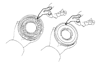
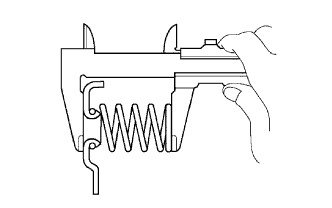
INSPECT FORWARD CLUTCH RETURN SPRING SUB-ASSEMBLY
-
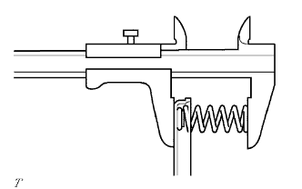
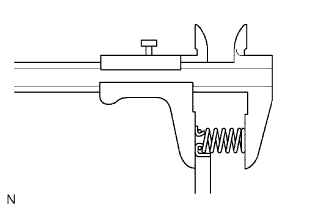
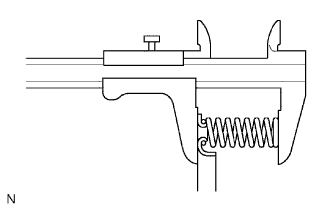
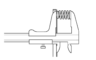
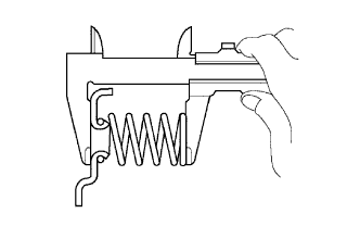
Using a vernier caliper, measure the free length of the spring together with the spring seat.
Standard free length 28.23 mm (1.1114 in.) If the result is not as specified, replace the spring.
-
-
REMOVE FORWARD CLUTCH PISTON SUB-ASSEMBLY
-
Place the forward clutch drum onto the oil pump.
-
Holding the forward clutch piston sub-assembly with your hand, apply compressed air (392 kPa, 4.0 kgf/cm2, 57 psi) to the oil pump to remove the forward clutch piston sub-assembly.
Tech Tips
When the piston is slanted and cannot be removed, remove it by pushing down the protruding side and applying compressed air again, or using need-nose pliers (with its tips wrapped in tape).
-
-
REMOVE FORWARD CLUTCH PISTON O-RING
-
Remove the 2 O-rings from the forward clutch piston sub-assembly.
-
-
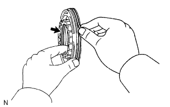
INSPECT FORWARD CLUTCH PISTON SUB-ASSEMBLY
-
Shake the piston to check that the check ball is not stuck.
-
Check that the valve does not leak when applying low compressed air (392 kPa, 4.0 kgf/cm2, 57 psi).
-
-
REMOVE INPUT SHAFT OIL SEAL RING
-
Remove the input shaft oil seal ring.
-
-
REMOVE MULTIPLE DISC CLUTCH HUB
-
Remove the thrust bearing, multiple clutch hub, thrust needle roller bearing and bearing race from the transaxle.
-
-
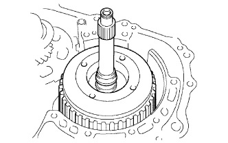
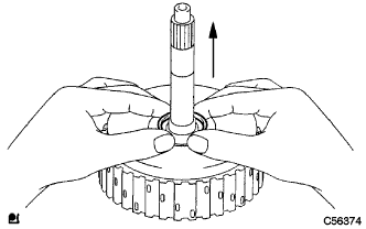
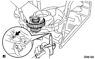
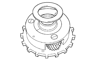
REMOVE UNDERDRIVE PLANETARY GEAR ASSEMBLY
-
Remove the bolt and parking lock pawl shaft clamp.
-
Remove the parking lock pawl shaft.
-
Push the parking lock pawl.
Tech Tips
Failure to do so will cause the interference when the underdrive planetary gear is removed.
-
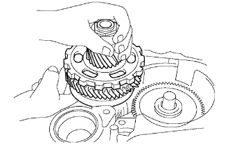
Remove the underdrive planetary gear assembly from the transaxle.
Note
Be careful so that the underdrive planetary gear assembly will not fall out.
-
Remove the tension spring, parking lock pawl pin and parking lock pawl.
-
-
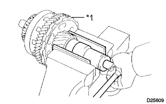
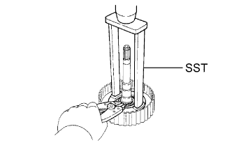
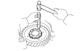
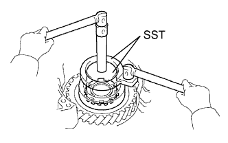
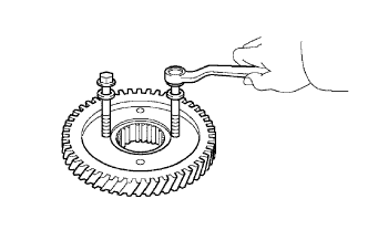
REMOVE FRONT PLANETARY GEAR NUT
-
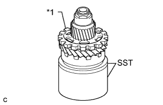
Text in Illustration *1 Underdrive Planetary Gear Using SST, secure the underdrive planetary gear assembly.
- SST
- 09387-00050
- 09495-65040
-
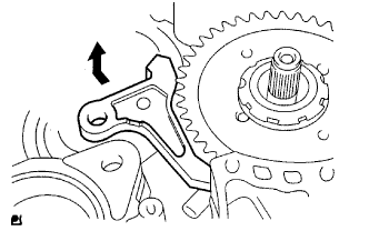
Using SST, loosen the staked part of the front planetary gear nut.
- SST
- 09930-00010 ( 09931-00010, 09931-00020 )
-
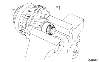
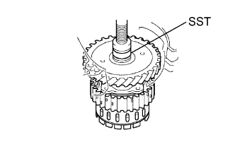
Text in Illustration *1 Underdrive Planetary Gear Clamp the underdrive planetary gear in a soft jaw vise.
Note
Be careful not to damage the differential drive pinion.
-
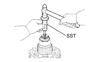
Text in Illustration *1 Underdrive Planetary Gear Using a socket wrench, remove the front planetary gear nut.
-
-
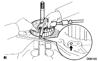
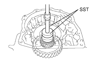
REMOVE CYLINDRICAL ROLLER BEARING INNER RACE
-
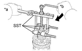
Text in Illustration *a Hold *b Turn Using SST, remove the cylindrical roller bearing inner race.
- SST
- 09950-00020
- 09950-00030
- 09950-40011 ( 09957-04010 )
- 09950-60010 ( 09951-00320 )
-
-
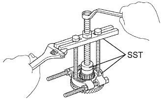
REMOVE UNDERDRIVE PLANETARY GEAR ASSEMBLY
-
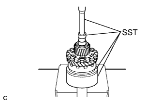
Using SST and a press, remove the differential drive pinion, parking lock gear, counter driven gear with underdrive planetary ring gear, underdrive angular ball bearing inner race (front side) and underdrive angular ball bearings.
- SST
- 09387-00050
- 09495-65040
- 09950-60010 ( 09951-00320 )
- 09950-70010 ( 09951-07100 )
-
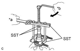
Text in Illustration *a Hold *b Turn Clamp the underdrive planetary gear in soft jaw vise.
-
Using SST, remove angular ball bearing inner race (rear side) from the underdrive planetary gear.
- SST
- 09950-00020
- 09950-00030
- 09950-40011 ( 09957-04010 )
- 09950-60010 ( 09951-00320 )
-
-
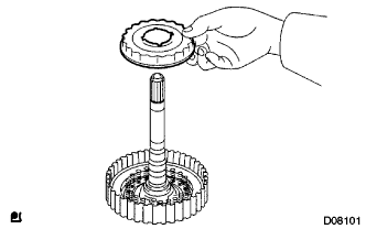
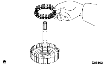
REMOVE UNDERDRIVE PLANETARY RING GEAR
-
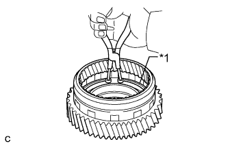
Text in Illustration *1 Snap Ring Using snap ring pliers, remove the underdrive planetary ring hole snap ring.
-
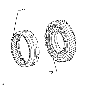
Text in Illustration *1 Underdrive Planetary Ring Gear *2 Counter Driven Gear Remove the underdrive planetary ring gear from the counter driven gear.
-
-
REMOVE UNDERDRIVE CLUTCH ASSEMBLY
-
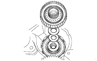
Remove the underdrive clutch assembly, needle roller bearing and No. 3 thrust bearing underdrive race from the transaxle.
-
-
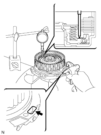
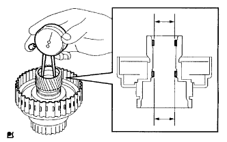
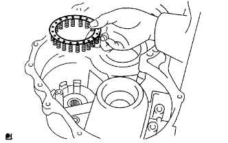
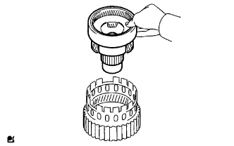
INSPECT UNDERDRIVE PACK CLEARANCE
-
Install the underdrive clutch to the transaxle case.
Note
Be careful not to damage the oil seal rings.
-
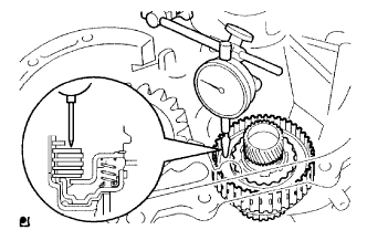
Install a dial indicator as shown in the illustration.
-
Measure the underdrive clutch pack clearance while applying and releasing compressed air (392 kPa, 4.0 kgf/cm2, 57 psi).
Standard pack clearance 1.51 to 1.90 mm (0.0594 to 0.0748 in.) If the pack clearance is not as specified, inspect the discs, plates and flange.
If the park clearance is not as specified, select another flange.
Tech Tips
There are 3 flanges in different thickness.
Standard flange thickness No. Thickness No. Thickness A 3.0 mm (0.118 in.) C 3.4 mm (0.134 in.) B 3.2 mm (0.126 in.) - -
-
-
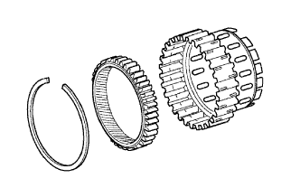
REMOVE NO. 1 UNDERDRIVE CLUTCH DISC SNAP RING
-
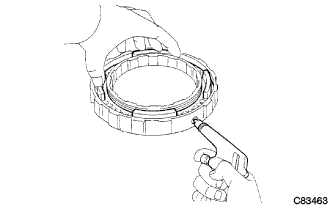
Text in Illustration *1 Protective Tape Using a screwdriver with its tip wrapped with protective tape, pry out the snap ring.
-
Remove the flange, 3 discs and 3 plates from the underdrive clutch drum.
-
-
INSPECT NO. 1 UNDERDRIVE CLUTCH DISC
-
Check to see if the sliding surface of the flange, discs and plates are worn or burnt. If necessary, replace them.
Tech Tips
-
If the lining of the disc is peeling off or discolored, or even if a part of the printed mark is defaced, replace all discs.
-
Before assembling new discs, soak them in ATF for at least 15 minutes.
-
-
-
REMOVE UNDERDRIVE CLUTCH PISTON SET
-
Place SST on the clutch balancer and compress the piston return spring with a press.
- SST
- 09350-32014 ( 09351-32070 )
-
Using a snap ring expander, remove the snap ring.
Note
-
Stop pressing when the spring seat is 1 to 2 mm (0.039 to 0.078 in.) below the snap ring groove to prevent the spring seat from being deformed.
-
Do not expand the snap ring excessively.
-
-
Remove the clutch balancer and piston return spring from the underdrive clutch drum.
-
Install the underdrive clutch drum to the transaxle case.
Note
Be careful not to damage the oil seal rings.
-
Holding the underdrive clutch piston with your hand, apply compressed air (392 kPa, 4.0 kgf/cm2, 57 psi) to the transaxle case to remove the underdrive clutch piston.
CAUTION:
Applying compressed air may cause the piston to jump out. When removing the piston, hold it with your hand using a piece of cloth.
Note
Do not splash ATF when applying compressed air.
-
-
INSPECT UNDERDRIVE CLUTCH RETURN SPRING SUB-ASSEMBLY
-
Using a vernier caliper, measure the free length of the spring together with the spring seat.
Standard free length 17.14 mm (0.6748 in.) If the result is not as specified, replace the spring.
-
-
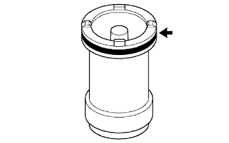
REMOVE UNDERDRIVE CLUTCH DRUM O-RING
-
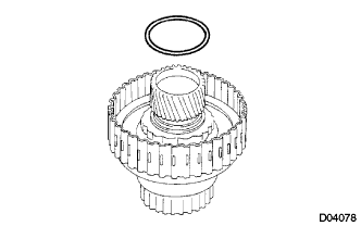
Remove the underdrive clutch drum O-ring.
-
-
INSPECT UNDERDRIVE CLUTCH DRUM SUB-ASSEMBLY
-
Using a caliper gauge, measure the inside diameter of the underdrive clutch drum bush.
Standard drum bush 32.56 to 32.58 mm (1.2818 to 1.2826 in.) Maximum drum bush 32.63 mm (1.2846 in.) If the inside diameter is greater than the maximum, replace the underdrive clutch drum sub-assembly.
-
-
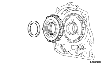
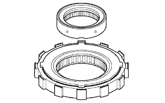
REMOVE UNDERDRIVE ONE-WAY CLUTCH ASSEMBLY
-
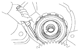
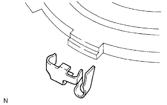
Using a screwdriver, pry out the snap ring from the transaxle.
-
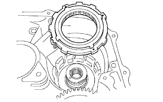
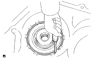
Remove the one-way clutch from the transaxle.
-
Remove the outer race retainer from the underdrive one-way clutch assembly.
-
-
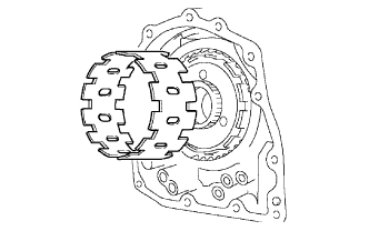
REMOVE NO. 2 UNDERDRIVE CLUTCH DISC
-
Using a screwdriver, pry out the snap ring from the transaxle.
-
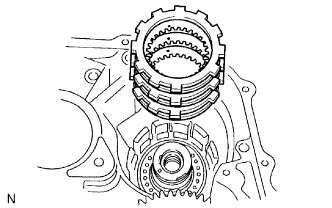
Remove the flange, 3 discs and 3 plates from the transaxle.
-
-
INSPECT NO. 2 UNDERDRIVE CLUTCH DISC
Check to see if the sliding surface of the flange, discs and plates are worn or burnt.
If necessary, replace them.
Tech Tips
-
If the lining of the disc is peeling off or discolored, or even if a part of the groove is defaced, replace all discs.
-
Before assembling new discs, soak them in ATF for at least 15 minutes.
-
-
REMOVE UNDERDRIVE BRAKE RETURN SPRING SUB-ASSEMBLY
-
Using SST, a snap ring expander and press, remove the snap ring from the transaxle.
- SST
- 09387-00020
-
Remove the underdrive brake return spring from the underdrive brake piston.
-
-
INSPECT UNDERDRIVE BRAKE RETURN SPRING SUB-ASSEMBLY
-
Using a vernier caliper, measure the free length of the underdrive brake return spring together with the spring seat.
Standard free length 14.04 mm (0.5213 in.) If the free length is shorter than the standard free length, replace the under drive brake return spring sub-assembly.
-
-
REMOVE UNDERDRIVE CLUTCH DRUM OIL SEAL RING
-
Remove the 2 underdrive clutch drum oil seal rings from the transaxle.
-
-
REMOVE UNDERDRIVE BRAKE PISTON
-
Apply compressed air (392 kPa, 4.0 kgf/cm2, 57 psi) to the transaxle case to remove the underdrive brake piston.
CAUTION:
Applying compressed air may cause the piston to jump out. When removing the piston, hold it with your hand using a piece of cloth.
Note
Do not splash ATF when applying compressed air.
-
Remove the 2 O-rings from the underdrive brake piston.
-
Using SST, remove the needle-roller bearing from the transaxle case.
- SST
- 09387-00041 ( 09387-01021, 09387-01030, 09387-01041 )
-
-
REMOVE NO. 1 TRANSAXLE CASE PLUG
-
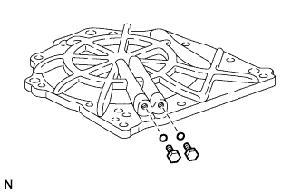
Remove the 2 No. 1 transaxle case plugs from the rear transaxle cover sub-assembly.
-
Remove the 2 O-rings from the 2 No. 1 transaxle case plugs.
-
-
REMOVE REAR TRANSAXLE COVER SUB-ASSEMBLY
-
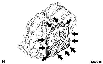
Remove the 11 bolts.
-
Tap the circumference of the rear transaxle cover sub-assembly with a plastic-faced hammer to remove the transaxle rear transaxle cover sub-assembly from the transaxle.
-
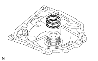
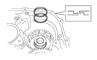
Remove the 2 outer rear clutch oil seal rings from the rear transaxle cover sub-assembly.
-
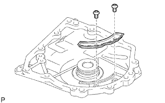
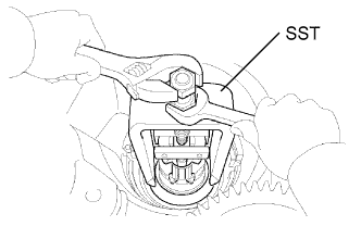
Using a T30 ''TORX'' socket wrench, remove the 2 screws and rear transaxle cover plate.
-
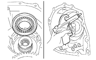
Using SST, remove the needle roller bearing from the rear transaxle cover sub-assembly.
- SST
- 09387-00041 ( 09387-01010, 09387-01030, 09387-01040 )
-
-
REMOVE BRAKE APPLY TUBE
-
Remove the bolt, No. 1 transaxle apply tube clamp and brake apply tube.
-
-
REMOVE FRONT CLUTCH APPLY TUBE
-
Remove the front clutch apply tube.
-
-
REMOVE NO. 1 GOVERNOR APPLY GASKET
-
Using a screwdriver, remove the 2 governor apply gaskets.
-
-
REMOVE DIRECT CLUTCH ASSEMBLY
-
Remove the thrust needle roller bearing and direct clutch assembly from the transaxle.
-
Remove the bearing race from the direct clutch assembly.
-
-
INSPECT PACK CLEARANCE OF DIRECT CLUTCH
-
Install the direct clutch and needle roller bearing on the transaxle rear cover.
-
Using a dial indicator, measure the direct clutch pack clearance while applying and releasing compressed air (392 kPa, 4.0 kgf/cm2, 57 psi).
Standard pack clearance 0.605 to 0.825 mm (0.02382 to 0.03248 in.) If the pack clearance is less than the minimum, parts may have been assembled incorrectly, so check and reassemble again.
If the stroke is not as specified, select another flange.
Tech Tips
There are 6 flanges in different thickness.
Standard Flange Thickness No. Thickness No. Thickness 1 3.0 mm (0.118 in.) 4 3.3 mm (0.130 in.) 2 3.1 mm (0.122 in.) 5 3.4 mm (0.134 in.) 3 3.2 mm (0.126 in.) 6 3.5 mm (0.138 in.)
-
-
REMOVE DIRECT MULTIPLE DISC CLUTCH DISC SNAP RING
-
Text in Illustration *1 Protective Tape Using a screwdriver with its tip wrapped with protective tape, pry out the direct multiple disc clutch disc snap ring from the direct clutch drum.
-
Remove the flange, 3 discs and 3 plates from the direct clutch drum.
-
-
INSPECT DIRECT MULTIPLE DISC CLUTCH DISC
-
Check to see if the sliding surface of the flange, discs and plates are worn or burnt.
If necessary, replace them.
Tech Tips
-
If the lining of the disc is peeling off or discolored, or even if a part of the printed mark is defaced, replace all discs.
-
Before assembling new discs, soak them in ATF for at least 15 minutes.
-
-
-
REMOVE DIRECT CLUTCH RETURN SPRING SUB-ASSEMBLY
-
Place SST on the clutch balancer and compress the direct clutch return spring sub-assembly with a press
- SST
- 09387-00020
-
Using a snap ring expander, remove the snap ring from the direct clutch drum.
Note
-
Stop pressing when the spring seat is 1 to 2 mm (0.039 to 0.078 in.) below the snap ring groove to prevent the spring seat from being deformed.
-
Do not expand the snap ring excessively.
-
-
Remove the clutch balancer from the direct clutch drum.
-
Remove the direct clutch return spring sub-assembly from the direct clutch drum.
-
Install the direct clutch drum on the rear transaxle cover sub-assembly.
-
Holding the direct clutch piston with your hand, apply compressed air (392 kPa, 4.0 kgf/cm2, 57 psi) to the rear transaxle cover sub-assembly to remove the direct clutch piston.
CAUTION:
Applying compressed air may cause the piston to jump out. When removing the piston, hold it with your hand using a piece of cloth.
Note
Do not splash ATF when applying compressed air.
-
-
INSPECT DIRECT CLUTCH RETURN SPRING SUB-ASSEMBLY
-
Using a vernier caliper, measure the free length of the spring together with the spring seat.
Standard free length 22.58 mm (0.8890 in.) If the result is not as specified, replace the spring.
-
-
REMOVE REAR PLANETARY SUN GEAR ASSEMBLY
-
Remove the rear planetary sun gear from the transaxle.
-
Remove the rear planetary sun gear thrust bearing from the rear planetary sun gear assembly.
-
Remove the No. 1 thrust washer and one-way clutch thrust bearing from the rear planetary sun gear assembly.
-
-
REMOVE ONE-WAY CLUTCH ASSEMBLY
-
Remove the No. 2 thrust washer and one-way clutch from the transaxle.
-
Remove the one-way clutch inner race from the one-way clutch assembly.
-
-
REMOVE OUTER ONE-WAY CLUTCH SLEEVE
-
Remove the outer one-way clutch sleeve.
-
-
REMOVE 2ND BRAKE CLUTCH DISC
-
Using a screwdriver, remove the snap ring.
-
Remove the flange, 3 discs and 3 plates from the transaxle.
-
-
INSPECT 2ND BRAKE CLUTCH DISC
-
Check to see if the sliding surface of the flange, discs and plates are worn or burnt.
If necessary, replace them.
Tech Tips
-
If the lining of the disc is peeling off or discolored, or even if a part of the printed number is defaced, replace all discs.
-
Before assembling new discs, soak them in ATF for at least 15 minutes.
-
-
-
REMOVE 2ND BRAKE PISTON ASSEMBLY
-
Using a screwdriver, pry out the snap ring.
-
Remove the 2nd brake piston assembly from the transaxle.
-
-
REMOVE 2ND BRAKE PISTON RETURN SPRING SUB-ASSEMBLY
-
Place SST on the 2nd brake piston return spring sub-assembly, and compress the 2nd brake piston return spring sub-assembly with a press.
- SST
- 09387-00060
-
Using a screwdriver, pry out the snap ring.
-
Remove the 2nd brake piston return spring sub-assembly.
-
-
INSPECT 2ND BRAKE PISTON RETURN SPRING SUB-ASSEMBLY
-
Using a vernier caliper, measure the free length of the spring together with the spring seat.
Standard free length 16.61 mm (0.6539 in.) If the result is not as specified, replace the spring.
-
-
REMOVE 2ND BRAKE PISTON
-
Hold the 2nd brake piston and apply compressed air (392 kPa, 4.0 kgf/cm2, 57 psi) to the 2nd brake cylinder to remove the 2nd brake piston.
CAUTION:
Applying compressed air may cause the piston to jump out. When removing the piston, hold it with your hand using a piece of cloth.
Note
Do not splash ATF when applying compressed air.
-
-
REMOVE 2ND BRAKE PISTON O-RING
-
Remove the 2 O-rings from the 2nd brake piston.
-
-
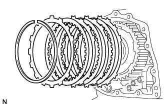
REMOVE 1ST AND REVERSE BRAKE CLUTCH DISC
-
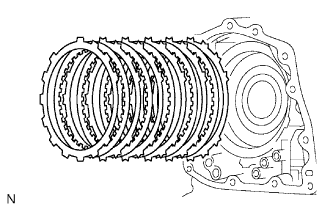
Remove the flange, 5 discs and 5 plates from the transaxle.
-
-
INSPECT 1ST AND REVERSE BRAKE CLUTCH DISC
-
Check to see if the sliding surface of the flange, discs and plates are worn or burnt.
If necessary, replace them.
Tech Tips
-
If the lining of the disc is peeling off or discolored, or even if a part of the groove is defaced, replace all discs.
-
Before assembling new discs, soak them in ATF for at least 15 minutes.
-
-
-
REMOVE REAR PLANETARY GEAR ASSEMBLY
-
Using a screwdriver, pry out the snap ring from the 2nd brake hub.
-
Remove the rear planetary gear assembly from the transaxle.
-
Remove the thrust washer from the rear planetary gear assembly.
-
Remove the No. 3 thrust bearing race from the rear planetary gear assembly.
-
-
REMOVE INPUT SUN GEAR
-
Remove the 2 thrust bearings, bearing race and input sun gear from the transaxle.
-
-
REMOVE FRONT PLANETARY GEAR ASSEMBLY
-
Using a chisel and hammer, unstake the lock washer.
Note
Push down all claws of the washer. Otherwise SST cannot be fully pressed against the nut and cannot loosen the nut.
-
Using SST, remove the lock nut and lock washer.
- SST
- 09387-00030
- 09387-00080
-
Using SST and a press, remove the front planetary gear assembly from the counter drive gear.
- SST
- 09950-60010 ( 09951-00450 )
-
Remove the front planetary gear assembly from the 2nd brake hub.
-
-
REMOVE FRONT PLANETARY RING GEAR
-
Using a screwdriver, pry out the brake hub snap ring and front planetary ring gear from the 2nd brake hub.
-
-
REMOVE 1ST AND REVERSE BRAKE PISTON
-
Using SST, a press and ring expander, remove the snap ring.
- SST
- 09387-00070
Note
-
Stop pressing when the spring seat is 1 to 2 mm (0.039 to 0.078 in.) below the snap ring groove to prevent the spring seat from being deformed.
-
Do not expand the snap ring excessively.
-
Remove the 1st and reverse brake return spring from the 1st and reverse brake piston.
-
Apply compressed air (392 kPa, 4.0 kgf/cm2, 57 psi) to the transaxle to remove the 1st and reverse brake piston.
CAUTION:
Applying compressed air may cause the piston to jump out. When removing the piston, hold it with your hand using a piece of cloth.
Note
Do not splash ATF when applying compressed air.
-
Remove the 2 O-rings from the 1st and reverse brake piston.
-
-
INSPECT 1ST AND REVERSE BRAKE RETURN SPRING SUB-ASSEMBLY
-
Using a vernier caliper, measure the free length of the 1st and reverse brake return spring together with the spring seat.
Standard free length 15.51 mm (0.6106 in.) If the free length is shorter than the standard free length, replace the 1st and reverse brake return spring sub-assembly.
-
-
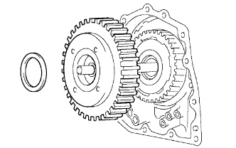
REMOVE COUNTER DRIVE GEAR
-
Using SST and a press, remove the counter drive gear and counter drive gear bearing (rear side) from the transaxle case.
- SST
- 09950-60010 ( 09951-00590 )
- 09950-70010 ( 09951-07100 )
-
As shown in the illustration, tighten the 2 bolts evenly and make a clearance of approximately 20.0 mm (0.797 in.) between the counter drive gear and the inner race.
-
Using SST, remove the counter drive gear bearing (front side).
- SST
- 09950-00020
- 09950-00030
- 09950-60010 ( 09951-00590 )
-
Using a brass bar and a hammer, tap out the 2 counter drive gear bearing outer races from the transaxle case.
-
-
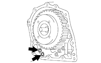
REMOVE COUNTER DRIVE GEAR HOLE SNAP RING
-
Using a screwdriver, pry out the counter drive gear hole snap ring from the transaxle case.
-
-
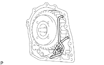
REMOVE DIFFERENTIAL GEAR LUBE APPLY TUBE
-
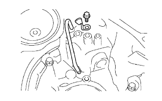
Remove the bolt, the No. 2 transaxle apply tube clamp and the differential gear lube apply tube from the transaxle housing.
-