AUTOMATIC TRANSAXLE UNIT REASSEMBLY

-
BEARING POSITION
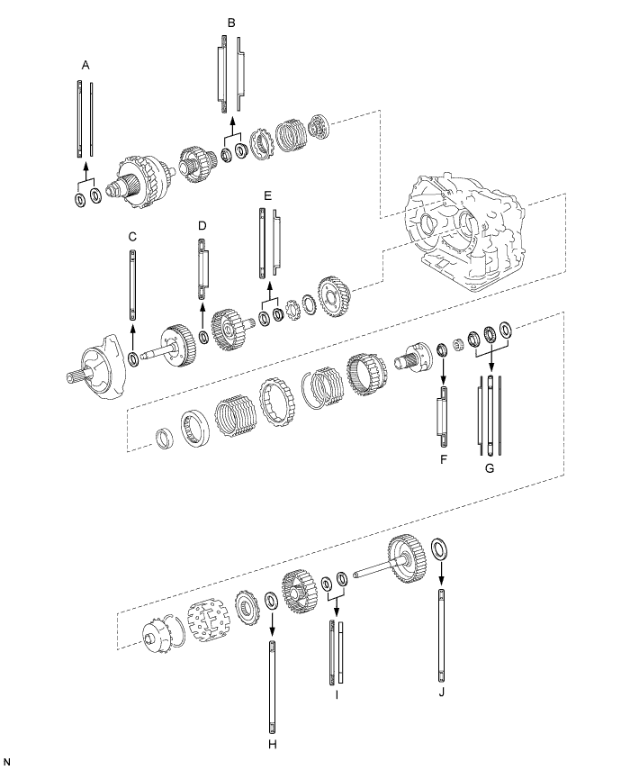
Standard bearing position Mark Front Race Diameter Inside / Outside Thrust Bearing Diameter Inside / Outside Rear Race Diameter Inside / Outside A - 53.0 mm (2.087 in.) / 78.2 mm (3.079 in.) 52.1 mm (2.051 in.) / 75.5 mm (2.972 in.) B - 37.73 mm (1.4854 in.) / 58.0 mm (2.283 in.) 29.9 mm (1.177 in.) / 55.5 mm (2.185 in.) C - 33.85 mm (1.3327 in.) / 52.2 mm (2.055 in.) - D - 23.5 mm (0.925 in.) / 44.0 mm (1.732 in.) - E - 36.3 mm (1.492 in.) / 52.2 mm (2.055 in.) 34.5 mm (1.358 in.) / 48.5 mm (1.909 in.) F - 34.6 mm (1.362 in.) / 52.2 mm (2.055 in.) - G 40.3 mm (1.587 in.) / 58.0 mm (2.283 in.) 38.6 mm (1.520 in.) / 60.0 mm (2.362 in.) 38.6 mm (1.520 in.) / 58.0 mm (2.283 in.) H - 53.6 mm (2.110 in.) / 69.6 mm (2.740 in.) - I - 33.7 mm (1.327 in.) / 48.2 mm (1.898 in.) 30.3 mm (1.193 in.) / 46.0 mm (1.811 in.) J - 53.6 mm (2.110 in.) / 70.18 mm (2.763 in.) or 69.6 mm (2.740 in.) - -
INSTALL DIFFERENTIAL GEAR LUBE APPLY TUBE
-
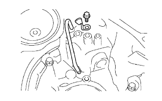
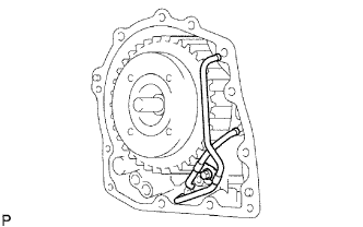
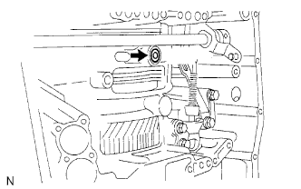
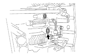
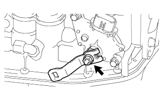
Install the differential gear lube apply tube and No. 2 transaxle apply tube clamp to the transaxle housing with the bolt.
- Torque:
- 9.8 N*m { 100 kgf*cm, 87 in.*lbf }
Note
Make sure to insert the tube to the stopper.
-
-
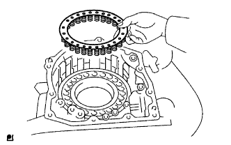
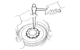
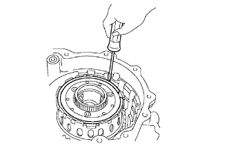
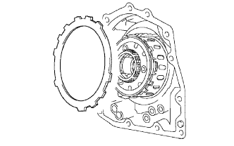
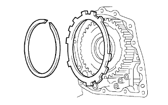
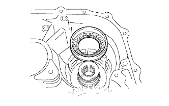
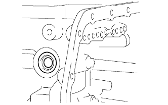
INSTALL COUNTER DRIVE GEAR HOLE SNAP RING
-
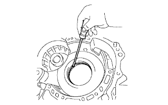
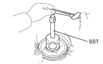
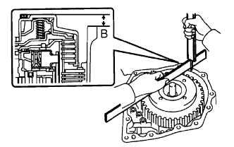
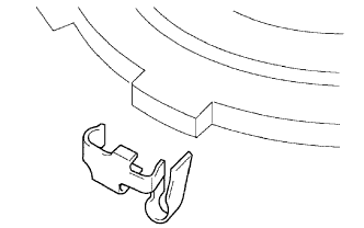
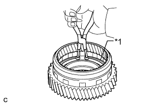
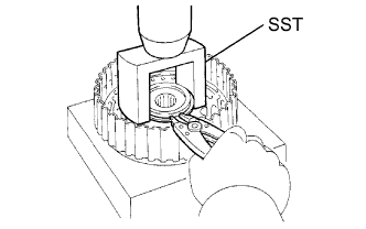
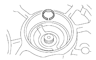
Using a screwdriver, install the counter drive gear hole snap ring to the transaxle.
-
-
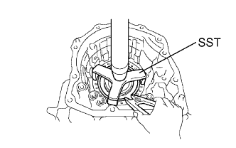
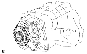
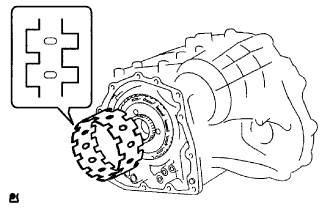
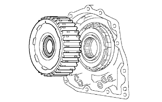
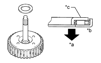
INSTALL COUNTER DRIVE GEAR
-
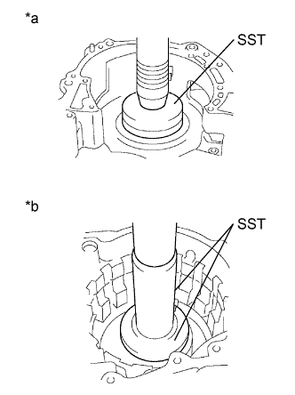
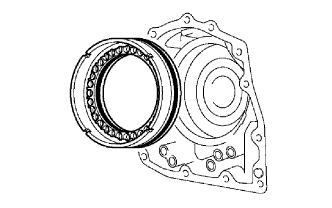
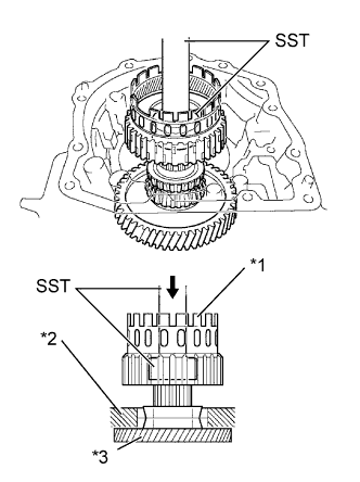
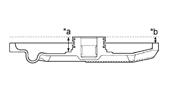
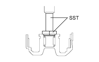
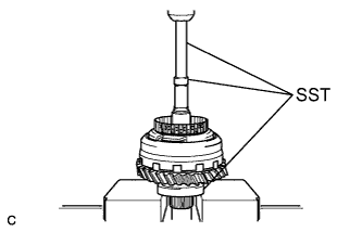
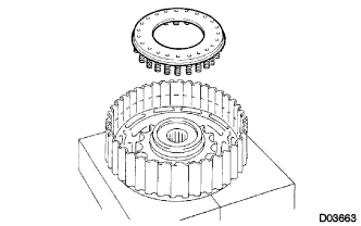
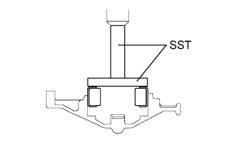
Text in Illustration *a Front side *b Rear side Using SST and a press, press in the 2 counter drive gear bearing outer races to the transaxle.
- SST
- 09950-60020 ( 09951-00890 )
- 09950-70010 ( 09951-07150 )
Note
-
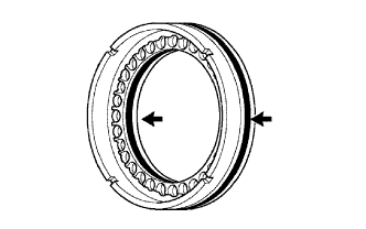
Press-fit the bearing race until it contacts the snap ring.
-
Do not apply excessive pressure.
-
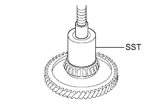
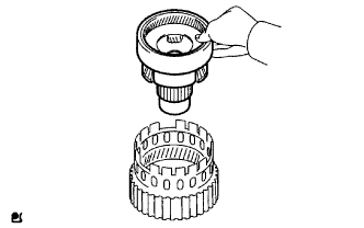
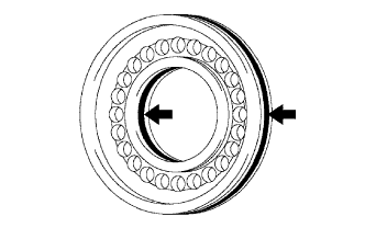
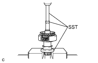
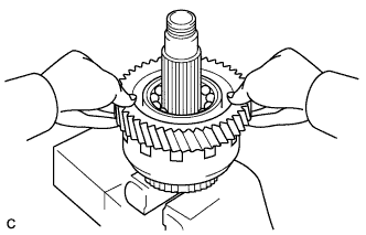
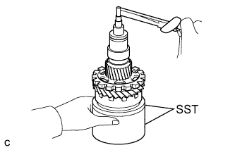
Using SST and a press, install the counter drive gear bearing (front side) to the counter drive gear.
- SST
- 09649-17010
Note
-
Press-fit the bearing inner race until it contacts the counter drive gear.
-
Do not apply excessive pressure.
-
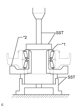
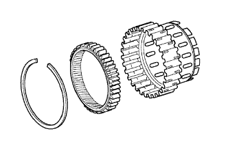
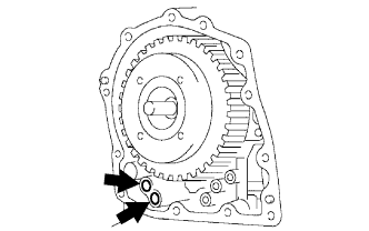
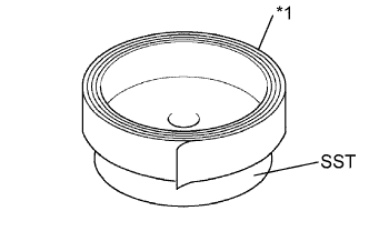
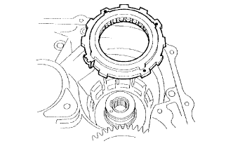
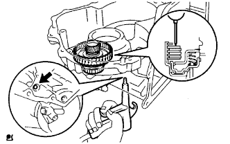
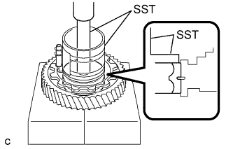
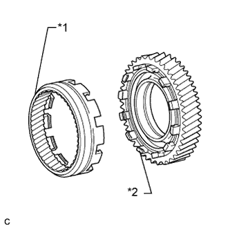
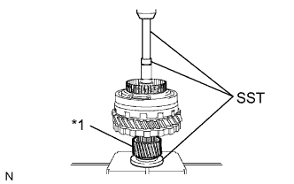
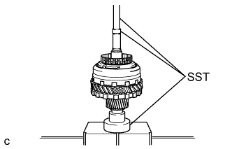
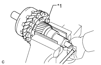
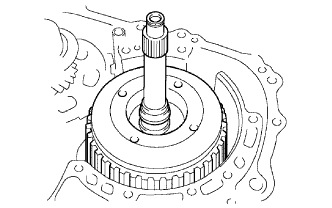
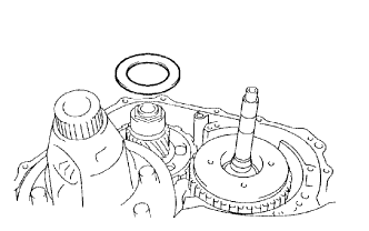
Text in Illustration *1 Counter Drive Gear Bearing (Rear Side) *2 Counter Drive Gear Using SST and a press, press in the counter drive gear and counter drive gear bearing (rear side) to the transaxle case.
- SST
- 09223-15030
- 09527-17011
- 09950-60020 ( 09951-00750 )
- 09950-70010 ( 09951-07150 )
Note
Do not apply excessive pressure.
-
-
INSTALL 1ST AND REVERSE BRAKE PISTON
-
Coat 2 new O-rings with ATF.
-
Install the 2 O-rings to the 1st and reverse brake piston.
-
Coat the 1st and reverse brake piston with ATF, and install it to the transaxle.
-
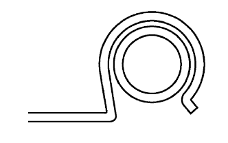
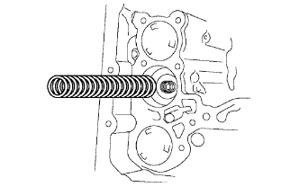
Install the 1st and reverse brake return spring to the 1st and reverse brake piston.
-
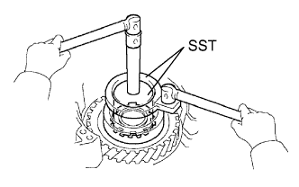
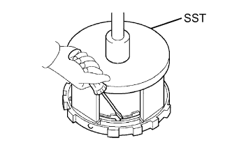
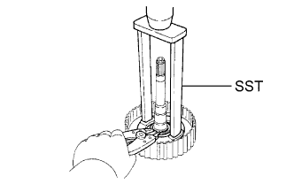
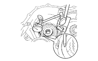
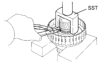
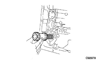
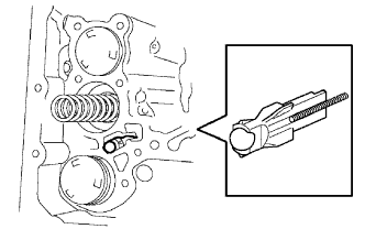
Using SST, a press and snap ring expander, press the 1st and reverse brake return spring and install the snap ring to the transaxle.
- SST
- 09387-00070
Note
-
Stop pressing when the spring seat is 1 to 2 mm (0.039 to 0.078 in.) below the snap ring groove to prevent the spring seat from being deformed.
-
Do not expand the snap ring excessively.
-
-
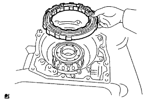
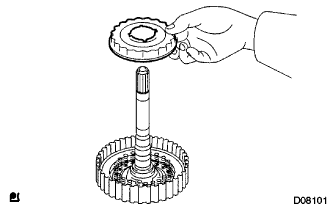
INSTALL FRONT PLANETARY RING GEAR
-
Using a screwdriver, install the front planetary ring gear and brake hub snap ring to the 2nd brake hub.
-
-
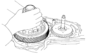
INSTALL FRONT PLANETARY GEAR ASSEMBLY
-
Install the front planetary gear assembly to the 2nd brake hub.
-
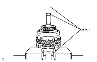
Text in Illustration *1 2nd Brake Hub with Front Planetary Gear *2 Transaxle Case *3 Counter Drive Gear Using SST and a press, press in the front planetary gear assembly and counter drive gear to the transaxle.
- SST
- 09950-60010 ( 09951-00400 )
- 09950-70010 ( 09951-07100 )
Note
Do not apply excessive pressure to it.
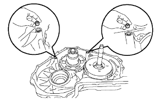
-
Install a new lock washer as shown in the illustration.
-
Using SST, install a new lock nut.
- SST
- 09387-00030
- 09387-00080
- Torque:
- 280 N*m { 2855 kgf*cm, 206 ft.*lbf }
-
Using SST and a torque wrench, measure the turning torque of the bearing while rotating SST at 60 rpm. When the measured value is not within the specified value, gradually tighten the lock nut until it reaches the specified value.
- SST
- 09387-00080
- Torque:
- Standard turning torque at 60 rpm
- 0.5 to 1.0 N*m { 5.1 to 10.0 kgf*cm, 4.4 to 8.7 in.*lbf, for new }
- 0.3 to 0.5 N*m { 3.1 to 5.1 kgf*cm, 2.7 to 4.4 in.*lbf, for used }
-
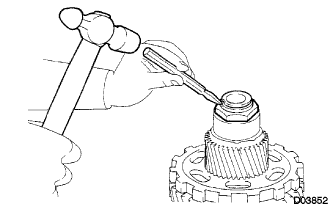
Using a chisel and hammer, stake the lock washer.
-
-
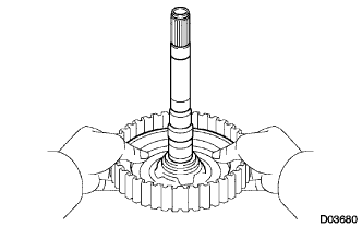
INSTALL INPUT SUN GEAR
-
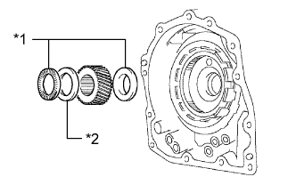
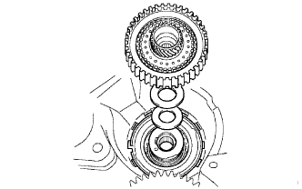
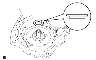
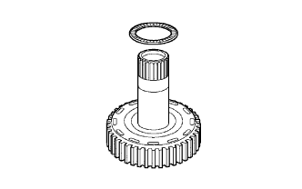
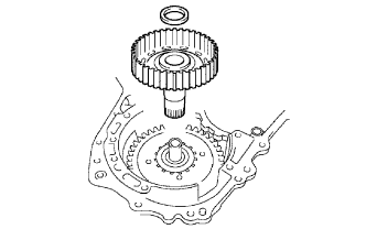
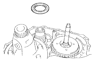
Text in Illustration *1 Thrust Bearing *2 Race Install the 2 thrust bearings, bearing race and input sun gear to the front planetary gear.
Standard Bearing Race Diameter Item Inside Outside Bearing 34.6 mm (1.362 in.) 52.2 mm (2.055 in.) Race 40.3 mm (1.587 in.) 58.0 mm (2.283 in.) Bearing 38.6 mm (1.520 in.) 60.0 mm (2.362 in.)
-
-
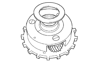
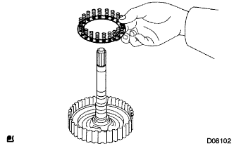
INSTALL REAR PLANETARY GEAR ASSEMBLY
-
Coat the No. 3 bearing race with ATF, and install it to the rear planetary gear assembly.
Standard Bearing Race Diameter Item Inside Outside Race 38.6 mm (1.520 in.) 58.0 mm (2.283 in.) -
Install the thrust washer to the rear planetary gear assembly.
-
Install the rear planetary gear assembly to the front planetary ring gear.
-
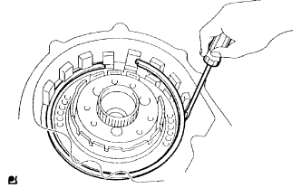
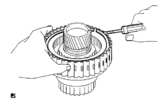
Using a screwdriver, install the snap ring to the 2nd brake hub.
-
-
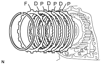
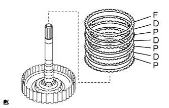
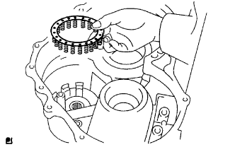
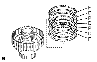
INSTALL 1ST AND REVERSE BRAKE CLUTCH DISC
-
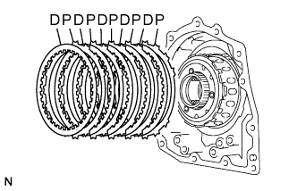
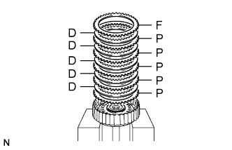
Install the 5 plates and 5 discs.
Install in order P - D - P - D - P - D - P - D - P - D Tech Tips
P = Plate
D = Disc
-
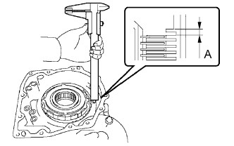
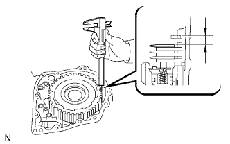
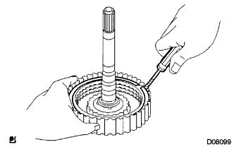
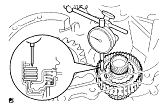
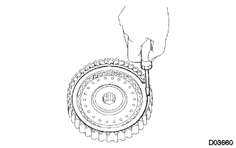
Using a vernier caliper, measure the distance between the disc surface and the contact surface of the 2nd brake hub and transaxle (Dimension A).
-
Select an appropriate flange so that the piston stroke will meet the specified value.
Pack clearance 1.02 to 1.21 mm (0.0402 to 0.0476 in.) Tech Tips
Piston stroke = Dimension A - Flange thickness
Standard Flange Thickness Mark Thickness Mark Thickness 1 1.8 mm (0.0709 in.) 5 2.2 mm (0.0866 in.) 2 1.9 mm (0.0748 in.) 6 2.3 mm (0.0905 in.) 3 2.0 mm (0.0787 in.) 7 2.4 mm (0.0945 in.) 4 2.1 mm (0.0827 in.) 8 2.5 mm (0.0984 in.) -
Install the flange.
-
-
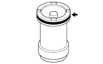
INSTALL OUTER ONE-WAY CLUTCH SLEEVE
-
Install the outer one-way clutch sleeve to the 2nd brake hub.
Note
Check the positioning direction of the outer sleeve.
-
-
INSTALL ONE-WAY CLUTCH ASSEMBLY
-
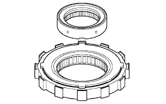
Install the one-way clutch inner race to the one-way clutch assembly.
Note
Check the direction of the inner race.
-
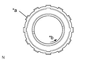
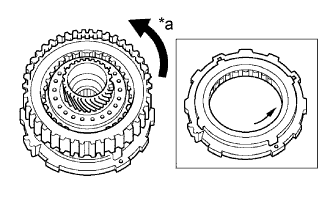
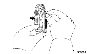
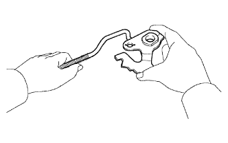
Text in Illustration *a Groove *b Free Check the rotating direction of the one-way clutch assembly for the lock or free operation as shown in illustration.
-
Install the one-way clutch assembly and No. 2 thrust washer to the outer one-way clutch sleeve.
Note
Install the thrust bearing properly so that no colored race will be visible.
-
-
INSTALL REAR PLANETARY SUN GEAR ASSEMBLY
-
Coat the No. 1 thrust washer with petroleum jelly, and install it onto the rear planetary sun gear assembly.
-
Coat the one-way clutch thrust bearing with petroleum jelly, and install it onto the rear planetary sun gear assembly.
Standard Bearing Diameter Item Inside Outside Bearing 53.6 mm (2.110 in.) 69.6 mm (2.740 in.) -
Coat the rear planetary sun gear thrust bearing with petroleum jelly, and install it onto the rear planetary sun gear assembly.
Standard Bearing Diameter Item Inside Outside Bearing 33.8 mm (1.331 in.) 48.2 mm (1.898 in.) -
Install the rear planetary sun gear assembly to the transaxle.
-
-
INSTALL 2ND BRAKE PISTON O-RING
-
Coat 2 new O-rings with ATF and install them onto the 2nd brake piston.
-
-
INSTALL 2ND BRAKE PISTON
-
Press the 2nd brake piston into the 2nd brake cylinder by hand.
-
-
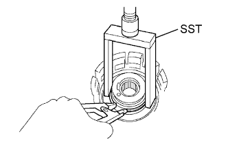
INSTALL 2ND BRAKE PISTON RETURN SPRING SUB-ASSEMBLY
-
Install the 2nd brake piston return spring sub-assembly.
-
Place SST on the 2nd brake piston return spring sub-assembly, and compress the 2nd brake piston return spring sub-assembly with a press.
- SST
- 09387-00060
-
Using a screwdriver, install the snap ring.
Note
Be sure that the end gap of the snap ring is not aligned with the piston return spring claw.
-
-
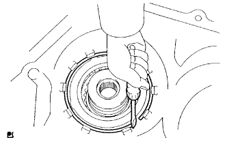
INSTALL 2ND BRAKE PISTON ASSEMBLY
-
Coat the 2nd brake piston assembly with ATF and install it to the transaxle.
-
Using a screwdriver, install the snap ring to the transaxle.
-
-
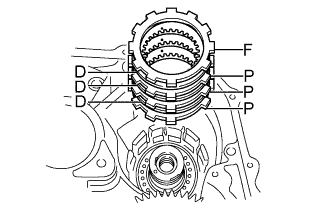
INSTALL 2ND BRAKE CLUTCH DISC
-
Install the 3 discs, 3 plates and flange to the transaxle.
Install in order P - D - P - D - P - D - F Tech Tips
P = Plate
D = Disc
F = Flange
-
Temporarily install the snap ring.
-
Using a vernier caliper, measure the distance between the disc surface and snap ring surface.
-
Select an appropriate flange so that the piston stroke will meet the specified value.
Standard pack clearance 0.62 to 0.91 mm (0.0244 to 0.0358 in.) Tech Tips
Piston stroke = Clearance - Flange thickness -Snap ring thickness 1.6 mm (0.063 in.)
Standard Flange Thickness Mark Thickness Mark Thickness 1 3.0 mm (0.118 in.) 5 3.4 mm (0.134 in.) 2 3.1 mm (0.122 in.) 6 3.5 mm (0.138 in.) 3 3.2 mm (0.126 in.) 7 3.6 mm (0.142 in.) 4 3.3 mm (0.130 in.) 8 - -
Temporarily remove the snap ring, attach the selected flange and restore the snap ring.
Note
Secure the snap ring so that its gap is visible through the groove of the transaxle case.
-
-
INSTALL DIRECT CLUTCH RETURN SPRING SUB-ASSEMBLY
-
Coat the direct clutch piston with ATF, and install it to the direct clutch drum.
Note
Be careful not to damage the lip seal of the direct clutch piston.
-
Install the direct clutch return spring sub-assembly to the direct clutch drum.
-
Install the clutch balancer to the direct clutch drum.
Note
Be careful not to damage the lip seal of the direct clutch balancer.
-
Place SST on the clutch balancer and compress the direct clutch return spring sub-assembly with a press.
- SST
- 09387-00020
-
Using a snap ring expander, install the snap ring to the direct clutch drum.
Note
-
Make sure that the end gap of the snap ring is not aligned with the clutch balancer claw.
-
Stop pressing when the spring seat is 1 to 2 mm (0.039 to 0.078 in.) below the snap ring groove to prevent the spring seat from being deformed.
-
Do not expand the snap ring excessively.
-
-
-
INSTALL DIRECT MULTIPLE DISC CLUTCH DISC SNAP RING
-
Install the 3 plates, 3 discs and flange.
Install in order P - D - P - D - P - D - F Tech Tips
P = Plate
D = Disc
F = Flange
-
Using a screwdriver, install the direct multiple disc clutch disc snap ring.
Tech Tips
Tape the screwdriver before use.
-
Check that the end gap of the direct multiple disc clutch disc snap ring is not aligned with any one of the cutouts.
-
-
INSPECT PACK CLEARANCE OF DIRECT CLUTCH
-
Install the direct clutch and needle roller bearing on the transaxle rear cover.
-
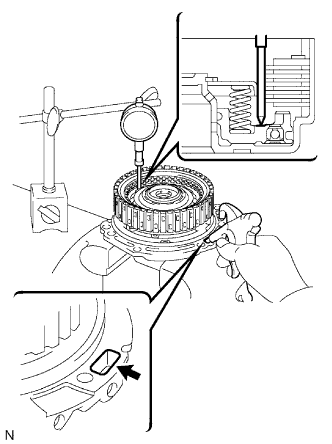
Using a dial indicator, measure the direct clutch pack clearance while applying and releasing compressed air (392 kPa, 4.0 kgf/cm2, 57 psi).
Standard pack clearance 0.605 to 0.825 mm (0.02382 to 0.03248 in.) If the pack clearance is less than the minimum, parts may have been assembled incorrectly, so check and reassemble again.
If the stroke is not as specified, select another flange.
Tech Tips
There are 6 flanges in different thickness.
Standard Flange Thickness No. Thickness No. Thickness 1 3.0 mm (0.118 in.) 4 3.3 mm (0.130 in.) 2 3.1 mm (0.122 in.) 5 3.4 mm (0.134 in.) 3 3.2 mm (0.126 in.) 6 3.5 mm (0.138 in.)
-
-
INSPECT DIRECT MULTIPLE DISC CLUTCH DISC
-
Check to see if the sliding surface of the flange, discs and plates are worn or burnt.
If necessary, replace them.
Tech Tips
-
If the lining of the disc is peeling off or discolored, or even if a part of the printed mark is defaced, replace all discs.
-
Before assembling new discs, soak them in ATF for at least 15 minutes.
-
-
-
INSTALL DIRECT CLUTCH ASSEMBLY
-
Install the bearing race to the direct clutch.
Standard Bearing Diameter Item Inside Outside Bearing race 30.3 mm (1.193 in.) 46.0 mm (1.811 in.) -
Install the direct clutch assembly and thrust needle roller bearing to the transaxle.
Note
The disc in the direct clutch should completely align with the hub attached outside the rear planetary sun gear. Otherwise, the rear cover cannot be installed.
-
Clean the connector part of the transaxle case and rear cover.
-
As shown in the illustration, place a straightedge on the direct clutch drum and measure the distance between the transaxle case and the straightedge using a vernier caliper (Dimension B).
-
Text in Illustration *a Dimension (1) *b Dimension (2) Measure the 2 places of the rear cover shown in the illustration and calculate dimension C using the following formula.
Tech Tips
Dimension C = Dimension (1) - Dimension (2)
-
Calculate the end play value using the following formula. Select a thrust bearing which satisfies the end play value and install it.
End play 0.198 to 0.936 mm (0.00800 to 0.03685 in.) Note
Make sure that the colored race side is facing the direct clutch assembly.
Tech Tips
End play = Dimension C - Dimension B
Standard Bearing Thickness and Diameter Thickness Inside Outside 3.58 mm (0.1409 in.) 53.6 mm (2.110 in.) 69.6 mm (2.740 in.) 3.88 mm (0.1528 in.) 53.6 mm (2.110 in.) 70.18 mm (2.763 in.)
-
-
INSTALL NO. 1 GOVERNOR APPLY GASKET
-
Install 2 new apply gaskets to the transaxle.
-
-
INSTALL FRONT CLUTCH APPLY TUBE
-
Install the No. 1 transaxle apply tube clamp to the front clutch apply tube.
Note
Make sure to install the clamp to the apply pipe before installing the apply pipe to the transaxle case. This prevents the apply pipe from being deformed or damaged.
-
-
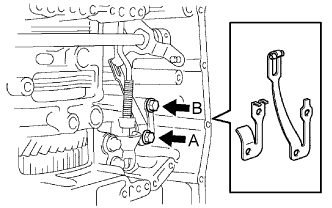
INSTALL BRAKE APPLY TUBE
-
Install the No. 1 transaxle apply tube clamp to the brake apply tube.
Note
Make sure to install the clamp to the apply tube before installing the apply tube to the transaxle case. This prevents the apply tube from being deformed or damaged.
-
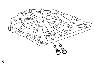
Install the 2 apply tubes to the transaxle with the bolt.
- Torque:
- 5.4 N*m { 55 kgf*cm, 48 in.*lbf }
Note
Each pipe should be securely inserted until it reaches the stopper.
-
-
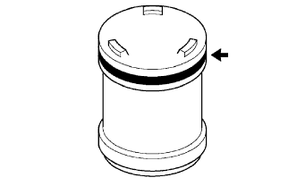
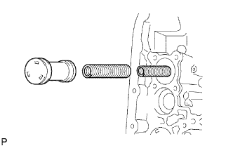
INSTALL NO. 1 TRANSAXLE CASE PLUG
-
Coat 2 new O-rings with ATF, and install them to the 2 No. 1 transaxle case plugs.
-
Install the 2 No. 1 transaxle case plugs to the rear transaxle cover sub-assembly.
- Torque:
- 7.4 N*m { 75 kgf*cm, 65 in.*lbf }
-
-
INSTALL REAR TRANSAXLE COVER SUB-ASSEMBLY
-
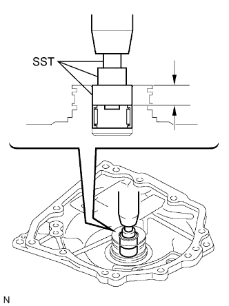
Using SST and a press, press in the needle roller bearing.
- SST
- 09950-60010 ( 09951-00200, 09951-00230, 09952-06010 )
Standard depth 12.05 to 12.75 mm (0.4744 to 0.5020 in.) Note
-
Face the inscribed mark side of the bearing race up.
-
Repeat the press-fit until the specified value is obtained.
-
Apply adhesive to the 2 screws.
Adhesive Toyota Genuine Adhesive 1344, Three Bond 1344 or Equivalent -
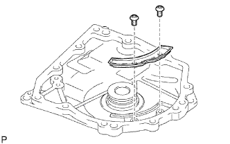
Using a T30 ''TORX'' socket, install the rear transaxle cover plate with the 2 screws.
- Torque:
- 7.5 N*m { 76 kgf*cm, 66 in.*lbf }
-
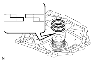
Coat 2 new outer rear clutch oil seal rings with ATF, and install them to the rear transaxle cover sub-assembly.
-
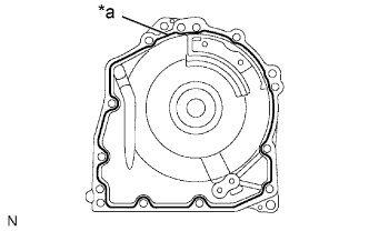
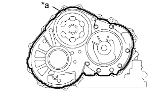
Text in Illustration *a Seal Packing Remove any packing material and be careful not to get oil on the contacting surfaces of the rear transaxle cover sub-assembly or the transaxle.
-
Apply seal packing to the rear transaxle cover sub-assembly.
Seal packing Toyota Genuine Seal Packing 1281, Three Bond 1281 or Equivalent -
Coat the needle roller bearing with ATF.
-
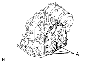
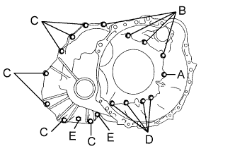
Apply adhesive to the threads of the bolts labeled A.
Adhesive Toyota Genuine Adhesive 1344, Three Bond 1344 or Equivalent -
Install the 11 bolts.
- Torque:
- 19 N*m { 194 kgf*cm, 14 ft.*lbf, for bolt A }
- 25 N*m { 255 kgf*cm, 18 ft.*lbf, for other bolts }
-
-
INSTALL UNDERDRIVE CLUTCH DRUM OIL SEAL RING
-
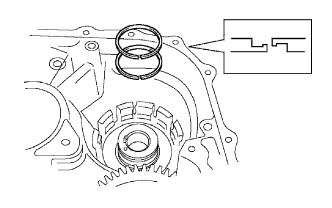
Install 2 new underdrive clutch drum oil seal rings to the transaxle.
-
-
INSTALL UNDERDRIVE BRAKE PISTON
-
Text in Illustration *1 Vinyl Tape Wind vinyl tape around SST 4.0 mm (0.157 in.) above from the bottom end until the thickness of the wound tape is about 5.0 mm (0.197 in.).
- SST
- 09550-60010 ( 09951-00320 )
Note
Clean SST to remove deposited oil before winding the vinyl tape.
-
Using SST and a press, press in the needle-roller bearing to the transaxle until the wound vinyl tape contacts the transaxle case.
- SST
- 09550-60010 ( 09951-00320 )
- 09950-70010 ( 09951-07100 )
-
Coat 2 new O-rings with ATF, and install them to the underdrive brake piston.
-
Install the underdrive brake piston to the transaxle.
-
-
INSTALL UNDERDRIVE BRAKE RETURN SPRING SUB-ASSEMBLY
-
Install the underdrive brake return spring to the underdrive brake piston.
-
Using SST, a snap ring expander and press, press the return spring and install the snap ring to the transaxle.
- SST
- 09387-00020
Note
Do not apply excessive pressure.
-
-
INSTALL NO. 2 UNDERDRIVE CLUTCH DISC
-
Install the flange, 3 discs and 3 plates to the transaxle.
Install in order P - D - P - D - P - D - F Tech Tips
D = Disc
P = Plate
F = Flange
-
Using a screwdriver, temporarily install the snap ring.
-
Using a dial indicator, measure the underdrive brake piston stroke while applying and releasing compressed air (392 kPa, 4.0 kgf/cm2, 57 psi).
Standard piston stroke 1.81 to 2.20 mm (0.0713 to 0.0866 in.) Tech Tips
Select an appropriate flange from the table below so that it will meet the specified value.
Standard Flange Thickness Mark Thickness Mark Thickness 1 3.0 mm (0.118 in.) 3 3.4 mm (0.134 in.) 2 3.2 mm (0.126 in.) - - -
Temporarily remove the snap ring, attach the flange and restore the snap ring.
-
-
INSTALL UNDERDRIVE ONE-WAY CLUTCH ASSEMBLY
-
Install the outer race retainer to the underdrive one-way clutch assembly.
-
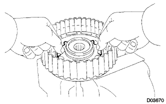
Text in Illustration *a Free Install the underdrive clutch assembly to the underdrive one-way clutch assembly. Rotate the underdrive clutch to check the rotating direction for the lock or free operation.
-
Install the underdrive one-way clutch assembly to the transaxle.
Note
Make sure that the mark on the one-way clutch outer race is visible.
-
Using a screwdriver, install the snap ring to the transaxle.
-
-
INSTALL UNDERDRIVE CLUTCH DRUM O-RING
-
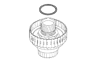
Coat a new O-ring with ATF and install it to the underdrive clutch drum.
-
-
INSTALL UNDERDRIVE CLUTCH PISTON SET
-
Coat the underdrive clutch piston with ATF, and install it to the underdrive clutch drum.
Note
Be careful not to damage the O-ring.
-
Install the piston return spring and clutch balancer to the underdrive clutch drum.
Note
Be careful not to damage the lip seal of the clutch balancer.
-
Place SST on the clutch balancer and compress the piston return spring with a press.
- SST
- 09350-32014 ( 09351-32070 )
-
Using a snap ring expander, install the snap ring to underdrive clutch drum.
Note
-
Be sure the end gap of the snap ring is not aligned with the clutch balancer's claw.
-
Stop pressing when the spring seat is 1 to 2 mm (0.039 to 0.078 in.) below the snap ring groove to prevent the spring seat from being deformed.
-
Do not expand the snap ring excessively.
-
-
-
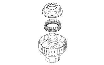
INSTALL NO. 1 UNDERDRIVE CLUTCH DISC SNAP RING
-
Install the 3 plates, 3 discs and flange.
Install in order P - D - P - D - P - D - F Tech Tips
P = Plate
D = Disc
F = Flange
-
Using a screwdriver, install the snap ring.
-
Check that the end gap of the snap ring is not aligned with one of the cutouts.
-
-
INSPECT UNDERDRIVE PACK CLEARANCE
-
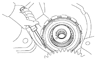
Install the underdrive clutch to the transaxle case.
Note
Be careful not to damage the oil seal rings.
-
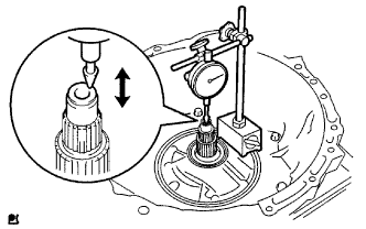
Install a dial indicator as shown in the illustration.
-
Measure the underdrive clutch pack clearance while applying and releasing compressed air (392 kPa, 4.0 kgf/cm2, 57 psi).
Standard pack clearance 1.51 to 1.90 mm (0.0594 to 0.0748 in.) If the pack clearance is not as specified, inspect the discs, plates and flange.
If the park clearance is not as specified, select another flange.
Tech Tips
There are 3 flanges in different thickness.
Standard flange thickness No. Thickness No. Thickness A 3.0 mm (0.118 in.) C 3.4 mm (0.134 in.) B 3.2 mm (0.126 in.) - -
-
-
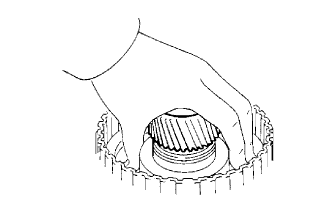
INSTALL UNDERDRIVE CLUTCH ASSEMBLY
-
Coat the needle roller bearing and No. 3 thrust bearing underdrive race with petroleum jelly, and install them onto the underdrive clutch assembly.
Standard Race Diameter Item Inside Outside Bearing 37.73 mm (1.4854 in.) 58.0 mm (2.283 in.) Race 29.9 mm (1.177 in.) 55.5 mm (2.185 in.) -
Install the underdrive clutch assembly to the transaxle.
-
-
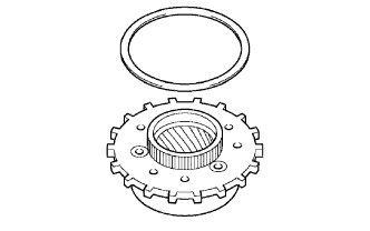
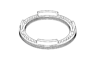
INSTALL UNDERDRIVE PLANETARY RING GEAR
-
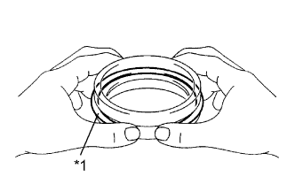
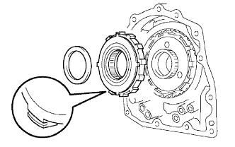
Text in Illustration *1 Snap Ring Install a new counter drive gear hole snap ring to a new underdrive angular ball bearing outer race.
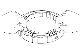
-
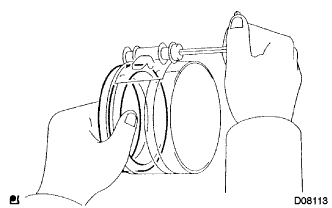
Using a piston ring compressor, squeeze the counter drive gear hole snap ring.
-
Using SST and a press, press in the underdrive angular ball bearing outer race.
- SST
- 09950-60020 ( 09951-00890 )
- 09950-70010 ( 09951-07100 )
-
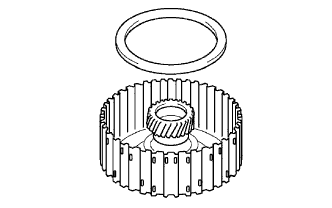
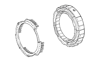
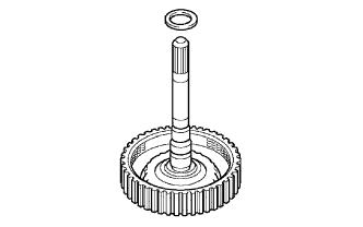
Text in Illustration *1 Underdrive Planetary Ring Gear *2 Counter Driven Gear Install the underdrive planetary ring gear to the counter driven gear.
-
Text in Illustration *1 Snap Ring Using snap ring pliers, install the underdrive planetary ring hole snap ring.
-
-
INSTALL UNDERDRIVE PLANETARY GEAR ASSEMBLY
-
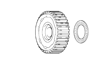
Using SST and a press, press a new angular ball bearing inner race (rear side) into the underdrive planetary gear assembly.
- SST
- 09726-40010
- 09950-60010 ( 09951-00260 )
- 09950-70010 ( 09951-07100 )
-
Install a new underdrive angular ball bearing (rear side) to the angular ball bearing inner race (rear side).
-
Install the counter driven gear with planetary ring gear and a new underdrive angular ball bearing (front side) to the underdrive planetary gear assembly.
-
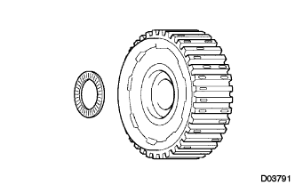
Using SST and a press, press in a new angular ball bearing inner race (front side).
- SST
- 09726-40010
- 09950-60010 ( 09951-00260 )
- 09950-70010 ( 09951-07100 )
Note
Rotate the counter driven gear while pressing.
-
Using SST and a press, press in the parking lock gear.
- SST
- 09316-20011
- 09950-60010 ( 09951-00260 )
- 09950-70010 ( 09951-07100 )
Note
Rotate the counter driven gear while pressing.
-
-
INSTALL DIFFERENTIAL DRIVE PINION
-
Text in Illustration *1 Differential Drive Pinion Using SST and a press, press in the differential drive pinion.
- SST
- 09726-40010
- 09950-60010 ( 09951-00260 )
- 09950-70010 ( 09951-07100 )
Note
Rotate the counter driven gear while pressing.
-
-
INSTALL CYLINDRICAL ROLLER BEARING INNER RACE
-
Using SST and a press, press in the cylindrical roller bearing inner race.
- SST
- 09515-21010
- 09950-60010 ( 09951-00260 )
- 09950-70010 ( 09951-07100 )
Note
Rotate the counter driven gear while pressing.
-
-
INSTALL FRONT PLANETARY GEAR NUT
-
Text in Illustration *1 Underdrive Planetary Gear Clamp the underdrive planetary gear in a soft jaw vise.
Note
Be careful not to damage the differential drive pinion.
-
Using a socket wrench, install a new front planetary gear nut.
- Torque:
- 280 N*m { 2855 kgf*cm, 206 ft.*lbf }
-
Using SST and a torque wrench, measure the turning torque of underdrive planetary gear assembly while rotating the torque wrench at 60 rpm.
- SST
- 09387-00050
- 09495-65040
- Torque:
- Standard turning torque at 60 rpm
- 0.23 to 5.01 N*m { 2 to 51 kgf*cm, 2.0 to 44.3 in.*lbf }
-
Using a pin punch and hammer, stake the front planetary gear nut.
Note
Make sure that there are no cracks on the nut.
-
-
INSTALL UNDERDRIVE PLANETARY GEAR ASSEMBLY
-
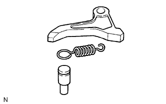
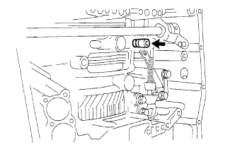
Install the parking lock pawl pin and torsion spring to the parking lock pawl.
-
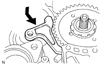
Temporarily install the parking lock pawl, parking lock pawl shaft and tension spring to the transaxle case as shown in the illustration.
-
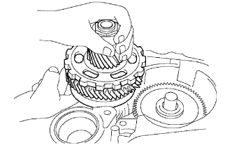
Install the underdrive planetary gear assembly to the transaxle.
Note
Engage all the discs of the underdrive clutch and hub splines of the underdrive planetary gear assembly firmly and assemble them securely.
-
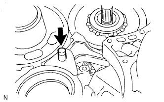
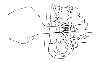
Install the parking lock pawl shaft.
-
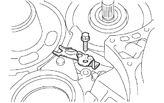
Install the parking lock pawl shaft clamp with the bolt.
- Torque:
- 9.8 N*m { 100 kgf*cm, 87 in.*lbf }
-
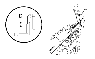
Using a straightedge and vernier caliper as shown in the illustration, measure the gap between the top of the differential drive pinion in the underdrive planetary gear and contact surface of the transaxle and housing (Dimension D).
Note
Note down the dimension D as it is necessary for the following process.
-
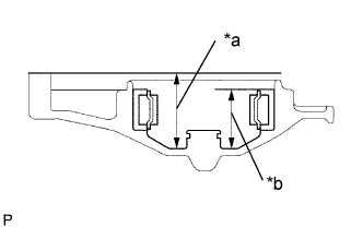
Text in Illustration *a Dimension (1) *b Dimension (2) As shown in the illustration, measure the 2 places of the transaxle housing. Calculate the dimension E using the formula.
Note
Note down the dimension E as it is necessary for the following process.
Tech Tips
Dimension E = Dimension (1) - Dimension (2)
-
-
INSPECT MULTIPLE DISC CLUTCH HUB
-
Using a caliper gauge, measure the inside diameter of the forward clutch hub bush.
Standard inside diameter 23.025 to 23.045 mm (0.9065 to 0.9073 in.) Maximum inside diameter 23.09 mm (0.9091 in.) Note
-
When the diameter is over the maximum, replace the multiple disc clutch hub with a new one.
-
Check the contact surface of the bush in the direct clutch shaft. If there are any scratches or discoloration, replace the direct clutch sub-assembly with a new one.
If the inside diameter is greater than the maximum, replace the forward clutch hub.
-
-
-
INSTALL MULTIPLE DISC CLUTCH HUB
-
Install the bearing race to the transaxle while checking its direction.
Standard Bearing Diameter Item Inside Outside Bearing race 34.5 mm (1.358 in.) 48.5 mm (1.909 in.) -
Coat the thrust needle roller bearing with petroleum jelly, and install it onto the multiple disc clutch hub.
Standard Thrust Bearing and Race Diameter Item Inside Outside Bearing 36.3 mm (1.429 in.) 52.25 mm (2.055 in.) -
Install the thrust bearing to the multiple clutch hub.
Standard Bearing Diameter Item Inside Outside Bearing 23.5 mm (0.925 in.) 44.0 mm (1.732 in.) -
Install the multiple disc clutch hub to the transaxle.
-
-
INSTALL INPUT SHAFT OIL SEAL RING
-
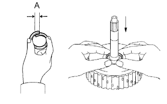
Compress a new input shaft oil seal ring from both sides to reduce dimension A.
Dimension A 5.0 mm (0.197 in.) -
Coat the oil seal ring with ATF and install it to the input shaft.
-
-
INSTALL FORWARD CLUTCH PISTON O-RING
-
Coat 2 new O-rings with ATF, and install them to the forward clutch piston sub-assembly.
-
-
INSTALL FORWARD CLUTCH PISTON SUB-ASSEMBLY
-
Install the forward clutch piston sub-assembly to the forward clutch drum.
-
-
INSTALL FORWARD CLUTCH RETURN SPRING SUB-ASSEMBLY
-
Place the forward clutch return spring sub-assembly onto the forward clutch piston.
-
Place SST on the forward clutch return spring sub-assembly, and compress the return spring with a press.
- SST
- 09350-32014 ( 09351-32070 )
-
Install the snap ring with a snap ring expander. Be sure the end gap of the snap ring is not aligned with the spring retainer claw.
Note
-
Stop pressing when the spring seat is 1 to 2 mm (0.039 to 0.078 in.) below the snap ring groove to prevent the spring seat from being deformed.
-
Do not expand the snap ring excessively.
-
-
-
INSTALL FORWARD CLUTCH FLANGE HOLE SNAP RING
-
Install the 5 plates, 5 discs and flange.
Install order P - D - P - D - P - D - P - D - P - D - F Tech Tips
P = Plate
D = Disc
F = Flange
-
Using a screwdriver, install the forward clutch flange hole snap ring.
-
Check that the end gap of the forward clutch flange hole snap ring is not aligned with one of the cutouts.
-
-
INSPECT PACK CLEARANCE OF FORWARD CLUTCH
-
Install the forward clutch on the oil pump.
Note
Be careful not to damage the oil seal ring of the oil pump.
-
Using a dial indicator, measure the forward clutch piston stroke while applying and releasing compressed air (392 kPa, 4.0 kgf/cm2, 57 psi).
Standard piston stroke 1.74 to 2.08 mm (0.0685 to 0.0819 in.) If the piston stroke is less than the minimum, the parts may have been assembled incorrectly. Check and reassemble again.
If the clearance is not as specified, select another flange.
Tech Tips
There are 5 different thicknesses of flanges.
Standard flange thickness No. Thickness No. Thickness 1 3.00 mm (0.1181 in.) 4 3.45 mm (0.1358 in.) 2 3.15 mm (0.1240 in.) 5 3.60 mm (0.1417 in.) 3 3.30 mm (0.1299 in.) - -
-
-
INSPECT FORWARD MULTIPLE DISC CLUTCH DISC
-
Check to see if the sliding surface of the flange, discs and plates are worn or burnt.
If necessary, replace them.
Tech Tips
-
If the lining of the disc is peeling off or discolored, replace all discs.
-
Before assembling new discs, soak them in ATF for at least 15 minutes.
-
-
-
INSTALL FORWARD CLUTCH ASSEMBLY
-
Text in Illustration *a Forward Clutch Side *b Race "A" *c Race "B" Install the thrust bearing to the forward clutch.
Standard Bearing Diameter Item Inside Outside Bearing 33.85 mm (1.3327 in.) 52.2 mm (2.055 in.) Note
Install the thrust bearing properly so that race "B" will be visible.
-
Install the forward clutch to the transaxle.
Note
Align the splines of all discs in the forward clutch with those of the multiple clutch hub to assemble them securely.
-
-
INSTALL OVERDRIVE BRAKE GASKET
-
Install 2 new overdrive brake gaskets to the transaxle.
-
-
INSTALL FRONT DIFFERENTIAL ASSEMBLY
-
Install the front differential assembly to the transaxle.
-
-
INSTALL NO. 2 THRUST BEARING UNDERDRIVE RACE
-
Install the thrust bearing race to the underdrive planetary gear assembly.
-
-
INSTALL THRUST NEEDLE ROLLER BEARING
-
Calculate the end play value using the following formula and value of dimensions D and E that were measured when installing the cylindrical roller bearing and underdrive planetary gear assembly. Select an appropriate underdrive planetary gear thrust bearing race No. 2 which satisfies the specified end play value, and install it.
Standard end play 0.498 to 0.993 mm (0.0194 to 0.0390 in.) Tech Tips
End play = Dimension E - Dimension D - thrust bearing thickness 3.28 mm (0.1291 in.) - underdrive thrust bearing race thickness.
Standard Race Thickness E - D Thickness Less then 7.34 mm (0.2890 in.) 3.5 mm (0.138 in.) 7.34 mm (0.2890 in.) 3.8 mm (0.150 in.) Standard Bearing and Bearing Race Diameter Item Inside Outside Bearing 53.0 mm (2.087 in.) 78.2 mm (3.079 in.) Bearing race 52.1 mm (2.051 in.) 75.5 mm (2.972 in.)
-
-
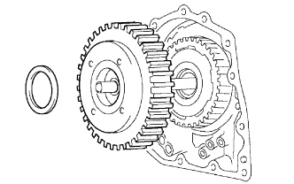
INSTALL OIL PUMP ASSEMBLY
-
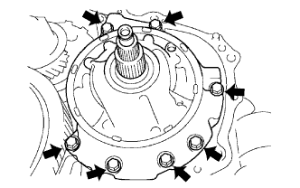
Install the oil pump assembly to the transaxle with the 7 bolts.
- Torque:
- 22 N*m { 226 kgf*cm, 16 ft.*lbf }
-
-
INSTALL UNDERDRIVE OUTPUT SHAFT OIL SEAL RING
-
Install a new underdrive output shaft oil seal ring to the transaxle housing.
-
-
INSTALL UNDERDRIVE CYLINDRICAL ROLLER BEARING
-
Using SST and a press, press in a new underdrive cylindrical roller bearing.
- SST
- 09950-60020
- 09950-70010 ( 09951-07100 )
Note
Do not apply excessive pressure to it.
-
-
INSTALL TRANSAXLE HOUSING
-
Text in Illustration *a Seal Packing
Seal Packing Diameter 1.2 mm (0.047 in.)
Remove any packing material and be careful not to get oil on the contacting surfaces of the transaxle case or transaxle housing.
-
Apply seal packing to the transaxle case.
Seal packing Toyota Genuine Seal Packing 1281, Three Bond 1281 or equivalent -
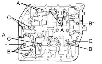
Install the transaxle housing to the transaxle with the 18 bolts.
- Torque:
- Bolt A
- 22 N*m { 224 kgf*cm, 16 ft.*lbf }
- Bolt B
- 29 N*m { 300 kgf*cm, 22 ft.*lbf }
- Bolt C
- 29 N*m { 300 kgf*cm, 22 ft.*lbf }
- Bolt D
- 22 N*m { 224 kgf*cm, 16 ft.*lbf }
- Bolt E
- 10 N*m { 102 kgf*cm, 7 ft.*lbf }
Tech Tips
Apply adhesive or equivalent to bolts A, D and E.
Adhesive Toyota Genuine Adhesive 1344, Three Bond 1344 or equivalent Bolt length Bolt A 72 mm (2.835 in.) Bolt B, D, E 50 mm (1.969 in.) Bolt C 42 mm (1.654 in.) Note
Apply adhesive to the bolts and tighten them within 10 minutes of application.
Seal packing Toyota Genuine Seal Packing 1281, Three Bond 1281 or equivalent
-
-
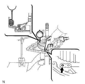
INSPECT INPUT SHAFT END PLAY
-
Secure the transaxle case with the oil pump side facing up.
-
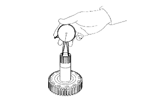
Using a dial indicator, measure the input shaft end play.
Standard end play 0.26 to 1.25 mm (0.0103 to 0.0492 in.) If the end play is not as specified, replace the stator shaft thrust needle roller bearing and the forward clutch hub thrust needle roller bearing.
-
-
SECURE AUTOMATIC TRANSAXLE ASSEMBLY
-
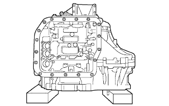
Place the transaxle assembly on wooden blocks.
-
-
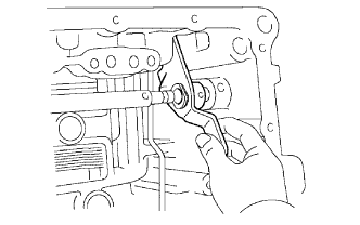
INSTALL MANUAL VALVE LEVER SHAFT OIL SEAL
-
Coat a new manual valve lever shaft oil seal with ATF, and install it to the transaxle.
-
-
INSTALL PARKING LOCK ROD SUB-ASSEMBLY
-
Install the parking lock rod sub-assembly to the manual valve lever sub-assembly.
-
-
INSTALL MANUAL VALVE LEVER SUB-ASSEMBLY
-
Install a new spacer and manual valve lever shaft to the transaxle.
-
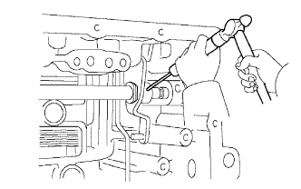
Using a pin punch and hammer, tap in a new manual valve lever shaft spring pin.
-
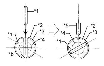
Text in Illustration *1 Pin *2 Spacer *3 Manual Valve Lever Sub-assembly *4 Manual Valve Lever Shaft *5 Pin Punch *a Staking Position Mark *b Small Hole Turn the spacer and manual valve lever shaft to align the small hole for locating the staking position in the spacer with the staking position mark on the manual valve lever shaft.
-
Using a pin punch, stake the spacer through the small hole.
-
Check that the spacer does not turn.
-
-
INSTALL MANUAL VALVE LEVER SHAFT RETAINER SPRING
-
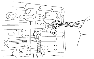
Using needle-nose pliers, install the manual valve lever shaft retainer spring.
-
-
INSTALL PARKING LOCK PAWL BRACKET
-
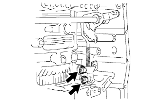
Install the parking lock pawl bracket with the 2 bolts.
- Torque:
- 20 N*m { 204 kgf*cm, 15 ft.*lbf }
Bolt length 25 mm (0.984 in.)
-
-
INSTALL MANUAL DETENT SPRING SUB-ASSEMBLY
-
Install the manual detent spring and spring cover with the 2 bolts.
Note
Make sure to install the manual detent spring and cover in this order.
- Torque:
- 20 N*m { 204 kgf*cm, 15 ft.*lbf, for bolt A }
- 12 N*m { 122 kgf*cm, 9 ft.*lbf, for bolt B }
Tech Tips
Each bolt length is indicated below.
Bolt length 27 mm (1.063 in.) for bolt A 16 mm (0.630 in.) for bolt B
-
-
INSTALL B-3 ACCUMULATOR PISTON
-
Coat a new O-ring with ATF, and install it to the B-3 accumulator piston.
-
Coat the B-3 accumulator piston and springs with ATF, and install them to the transaxle.
Standard Accumulator Spring Spring Free length
Outer diameter
Color B-3 Inner 60.24 mm (2.3716 in.)
15.9 mm (0.626)
Yellowish green B-3 Outer 74.61 mm (2.9374 in.)
21.7 mm (0.854 in.)
Blue
-
-
INSTALL C-1 ACCUMULATOR PISTON
-
Coat 2 new O-rings with ATF, and install them to the C-1 accumulator piston.
-
Coat the C-1 accumulator piston and spring with ATF, and install them to the transaxle.
Standard Accumulator Spring Spring Free length
Outer diameter
Color C-1 81.53 mm (3.2098 in.)
18.5 mm (0.728 in.)
Pink
-
-
INSTALL C-3 ACCUMULATOR PISTON
-
Coat a new O-ring with ATF, and install it to the C-3 accumulator piston.
-
Coat the C-3 accumulator piston with ATF, and install it to the transaxle.
-
Install the spring to the C-3 accumulator piston.
-
-
INSTALL CHECK BALL BODY
-
Install the check ball body and spring.
-
-
INSTALL TRANSMISSION WIRE
-
Coat a new O-ring with ATF, and install it to the transmission wire.
-
Install the transmission wire retaining bolt.
- Torque:
- 5.4 N*m { 55 kgf*cm, 48 in.*lbf }
-
-
INSTALL BRAKE DRUM GASKET
-
Coat a new brake drum gasket with ATF, and install it to the transaxle.
-
-
INSTALL TRANSAXLE CASE 2ND BRAKE GASKET
-
Coat a new transaxle case 2nd brake gasket with ATF, and install it to the transaxle.
-
-
INSTALL NO. 1 GOVERNOR APPLY GASKET
-
Coat a new No. 1 governor apply gasket with ATF, and install it to the transaxle.
-
-
INSTALL TRANSMISSION VALVE BODY ASSEMBLY
-
Make sure that the manual valve lever position, install the valve body with the 17 bolts to the transaxle.
- Torque:
- 11 N*m { 112 kgf*cm, 8 ft.*lbf }
Tech Tips
Each bolt length is indicated below.
Bolt length 25 mm (0.984 in.) for bolt A 41 mm (1.614 in.) for bolt B 45 mm (1.771 in.) for bolt C Note
-
Push the valve body against the accumulator piston spring and the check ball body to install it.
-
When installing the valve body to the transaxle case, do not hold the solenoids.
-
Tighten the bolts marked by * in the illustration first temporarily because they are positioning bolts.
-
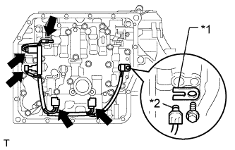
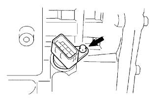
Text in Illustration *1 Lock Plate *2 O-ring Connect the 5 connectors.
-
Coat the O-ring with ATF.
-
Install the ATF temperature sensor, lock plate and bolt.
- Torque:
- 6.6 N*m { 67 kgf*cm, 58 in.*lbf }
-
-
INSTALL VALVE BODY OIL STRAINER ASSEMBLY
-
Coat a new O-ring with ATF, and install it to the valve body oil strainer assembly.
-
Install the valve body oil strainer assembly to the valve body with the 3 bolts.
- Torque:
- 11 N*m { 112 kgf*cm, 8 ft.*lbf }
-
-
INSTALL AUTOMATIC TRANSAXLE OIL PAN SUB-ASSEMBLY
-
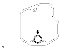
Text in Illustration *1 Magnet Install the 3 magnets in the automatic transaxle oil pan sub-assembly.
-
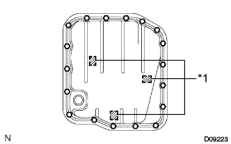
Install a new gasket to the automatic transaxle oil pan sub-assembly.
-
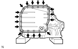
Install the automatic transaxle oil pan sub-assembly to the transaxle with the 18 bolts.
- Torque:
- 7.6 N*m { 77 kgf*cm, 67 in.*lbf }
Note
Because the bolts are seal bolts, apply seal packing to new bolts and tighten them within 10 minutes after application.
-
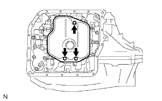
Install a new gasket and the drain plug.
- Torque:
- 47 N*m { 479 kgf*cm, 35 ft.*lbf }
-
-
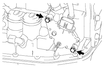
INSTALL SPEED SENSOR
-
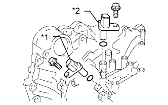
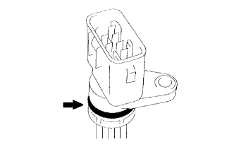
Text in Illustration *1 Speed Sensor NT *2 Speed Sensor NC Coat 2 new O-rings with ATF, and install them to the 2 speed sensors.
-
Install the 2 speed sensors with the 2 bolts to the transaxle.
- Torque:
- 11 N*m { 115 kgf*cm, 8 ft.*lbf }
-
-
INSTALL OIL COOLER INLET TUBE UNION
-
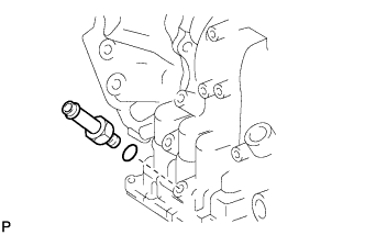
Coat a new O-ring with ATF, and install it to the oil cooler inlet tube union.
-
Install the oil cooler inlet tube union to the transaxle.
- Torque:
- 27 N*m { 275 kgf*cm, 20 ft.*lbf }
-
-
INSTALL OIL COOLER OUTLET TUBE UNION
-

Coat a new O-ring with ATF, and install it to the oil cooler outlet tube union.
-
Install the oil cooler outlet tube union to the transaxle case.
- Torque:
- 25 N*m { 255 kgf*cm, 18 ft.*lbf }
-
-
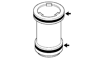
INSTALL NO. 1 TRANSAXLE CASE PLUG
-
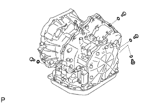
Coat 4 new O-rings with ATF, and install them to the 4 No. 1 transaxle case plugs.
-
Install the 4 No. 1 transaxle case plugs to the transaxle.
- Torque:
- 7.4 N*m { 75 kgf*cm, 65 in.*lbf }
-
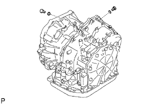
Coat 2 new O-rings with ATF, and install them to the 2 No. 1 transaxle case plugs.
-
Install the 2 No. 1 transaxle case plugs to the transaxle housing.
- Torque:
- 7.4 N*m { 75 kgf*cm, 65 in.*lbf }
-
-
INSTALL NO. 2 BREATHER PLUG
-
Coat a new O-ring with ATF, and install it to the No. 2 breather plug.
-
Install the No. 2 breather plug to the transaxle.
-
-
INSTALL BREATHER PLUG HOSE
-
Install the breather plug hose to the No. 2 breather plug.
-
-
INSTALL BREATHER PLUG SUB-ASSEMBLY
-
Install the breather plug sub-assembly to the breather plug hose.
-
-
INSTALL PARK/NEUTRAL POSITION SWITCH ASSEMBLY
-
Install the park/neutral position switch assembly onto the manual valve lever shaft and temporarily install the 2 bolts.
-
Install a new lock plate and the nut.
- Torque:
- 6.9 N*m { 70 kgf*cm, 61 in.*lbf }
-
Temporarily install the control shaft lever.
-
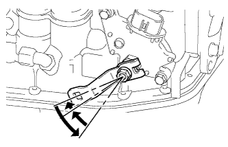
Turn the lever counterclockwise until it stops, and then turn it clockwise 2 notches.
-
Remove the control shaft lever.
-
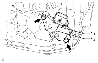
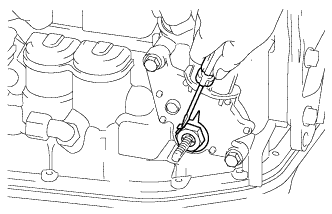
Text in Illustration *a Neutral Basic Line *b Nut Stopper Protrusion Align the groove with neutral basic line.
-
Tighten the 2 bolts.
- Torque:
- 5.4 N*m { 55 kgf*cm, 48 in.*lbf }
-
Using a screwdriver, stake the nut with the lock plate.
-
Install the control shaft lever, washer and nut.
- Torque:
- 13 N*m { 133 kgf*cm, 10 ft.*lbf }
-
-
INSTALL SPEEDOMETER DRIVEN HOLE COVER SUB-ASSEMBLY
-
Coat a new O-ring with ATF, and install it to the speedometer driven hole cover sub-assembly.
-
Install the speedometer driven hole cover sub-assembly with the bolt to the transaxle.
- Torque:
- 5.5 N*m { 56 kgf*cm, 49 in.*lbf }
-