OIL PUMP INSTALLATION

-
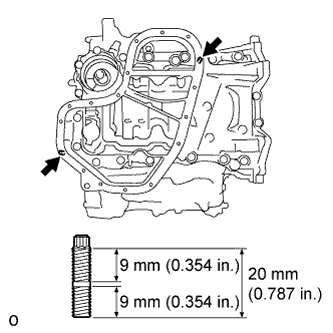
INSTALL TIMING CHAIN CASE OIL SEAL
-
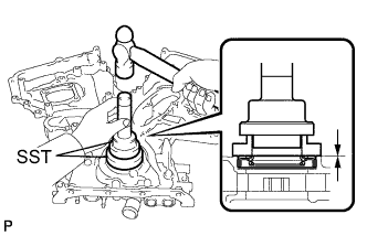
Using SST, tap in a new oil seal until its surface is flush with the timing chain case edge.
- SST
- 09223-22010
- 09506-35010
Note
-
Keep the lip free from foreign matter.
-
Do not tap on the oil seal at an angle.
-
Make sure that the oil seal edge does not stick out of the timing chain case.
-
-
INSTALL TIMING CHAIN COVER SUB-ASSEMBLY
-
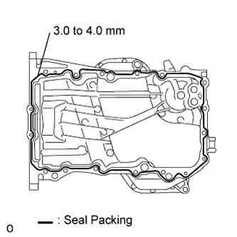
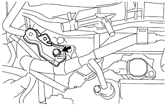
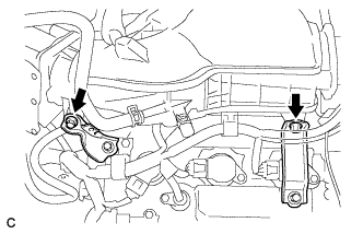
Apply seal packing in a continuous line to the engine unit as shown in the following illustration.
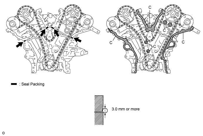
Seal packing Toyota Genuine Seal Packing Black, Three Bond 1207B or equivalent Seal diameter 3.0 mm (0.118 in.) Note
-
Be sure to clean and degrease the contact surfaces, especially the surfaces indicated by C in the illustration.
-
When the contact surfaces are wet, wipe them with an oil-free cloth before applying seal packing.
-
Install the chain cover within 3 minutes.
-
Do not start the engine for at least 2 hours after installing.
-
-
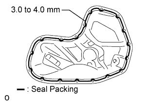
Apply seal packing in a continuous line to the timing chain cover as shown in the following illustration.
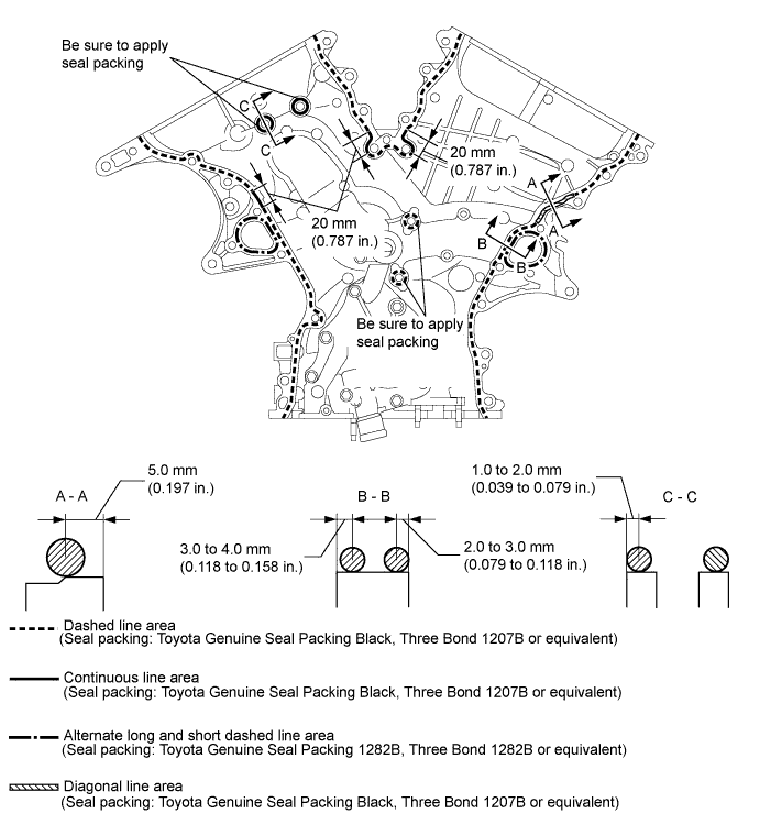
Seal packing Toyota Genuine Seal Packing Black, Three Bond 1207B or equivalent Toyota Genuine Seal Packing 1282B, Three Bond 1282B or equivalent Note
-
When the contact surfaces are wet, wipe them with an oil-free cloth before applying seal packing.
-
Install the chain cover within 3 minutes and tighten the bolts within 15 minutes after applying seal packing.
-
Do not start the engine for at least 2 hours after installing it.
Seal Packing Chart Area Seal Packing Diameter Application Position from Inside Seal Line Continuous Line Area 4.5 mm (0.177 in.) or more 3.0 to 4.0 mm (0.118 to 0.158 in.) Alternate Long and Short Dashed Line Area 3.5 mm (0.138 in.) or more 2.0 to 3.0 mm (0.0787 to 0.118 in.) Dashed Line Area 3.5 mm (0.138 in.) or more 3.0 to 4.0 mm (0.118 to 0.158 in.) Diagonal Line Area 6.0 mm (0.236 in.) or more 5.0 mm (0.197 in.) -
-
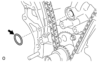
Install a new gasket.
-
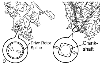
Align the oil pump drive rotor spline and the crankshaft as shown in the illustration. Install the spline and chain cover to the crankshaft.
-
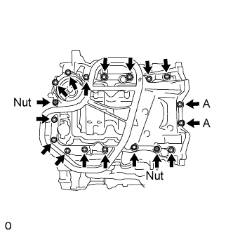
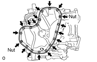
Temporarily tighten the timing chain cover with the 23 bolts and 2 nuts.
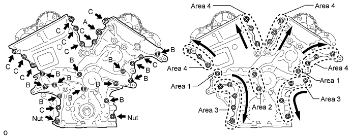
Bolt Length Item Length Bolt A 40 mm (1.57 in.) Bolt B 55 mm (2.17 in.) Bolt C 25 mm (0.984 in.) Note
Make sure that there is no oil on the bolt threads.
-
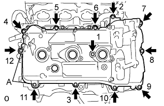
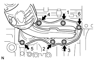
Fully tighten the bolts in Area 1 and Area 2.
- Torque:
- 21 N*m { 214 kgf*cm, 15 ft.*lbf }
-
Fully tighten the bolts and nuts in Area 3.
- Torque:
- 21 N*m { 214 kgf*cm, 15 ft.*lbf }
Tech Tips
Tighten the bolts and nuts from top to bottom as shown in the illustration.
-
Fully tighten the bolts in Area 4.
- Torque:
- Bolt A
- 43 N*m { 438 kgf*cm, 32 ft.*lbf }
- Except bolt A
- 21 N*m { 214 kgf*cm, 15 ft.*lbf }
Tech Tips
Tighten the bolts from bottom to top as shown in the illustration.
-
-
INSTALL OIL PAN SUB-ASSEMBLY
-
When replacing one of the stud bolts, install it using an E8 "TORX" socket wrench.
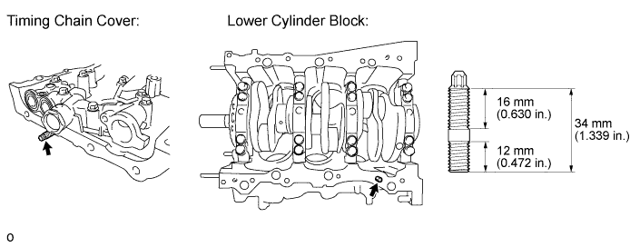
- Torque:
- 10 N*m { 102 kgf*cm, 7 ft.*lbf }
-
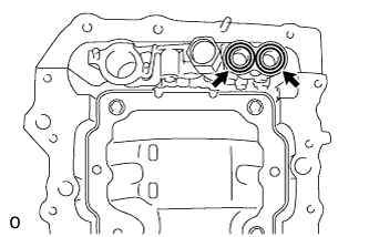
Install 2 new O-rings.
-
Apply seal packing in a continuous line as shown in the illustration.
Seal packing Toyota Genuine Seal Packing Black, Three Bond 1207B or equivalent Seal diameter 3.0 to 4.0 mm (0.118 to 0.157 in.) Note
-
Remove any oil from the contact surface.
-
Install the oil pan within 3 minutes after applying seal packing.
-
Do not start the engine for at least 2 hours after installing.
-
-
Install the oil pan with the 16 bolts and 2 nuts.
- Torque:
- Bolts A
- 10 N*m { 102 kgf*cm, 7 ft.*lbf }
- Except bolts A
- 21 N*m { 214 kgf*cm, 15 ft.*lbf }
-
-
INSTALL OIL STRAINER SUB-ASSEMBLY
-
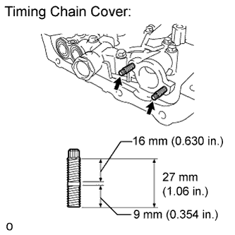
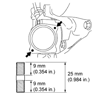
Using an E6 "TORX" socket, install the stud bolts as shown in the illustration.
- Torque:
- 4.0 N*m { 41 kgf*cm, 35 in.*lbf }
-
Install a new gasket and the oil strainer sub-assembly with the bolt and 2 nuts.
- Torque:
- 10 N*m { 102 kgf*cm, 7 ft.*lbf }
-
-
INSTALL NO. 2 OIL PAN SUB-ASSEMBLY
-
Using an E6 "TORX" socket, install the stud bolts as shown in the illustration.
- Torque:
- 4.0 N*m { 41 kgf*cm, 35 in.*lbf }
-
Apply seal packing in a continuous line as shown in the illustration.
Seal packing Toyota Genuine Seal Packing Black, Three Bond 1207B or equivalent Seal diameter 3.0 to 4.0 mm (0.118 to 0.157 in.) Note
-
Remove any oil from the contact surface.
-
Install the No. 2 oil pan sub-assembly within 3 minutes after applying seal packing.
-
Do not start the engine for at least 2 hours after installing.
-
-
Install the No. 2 oil pan sub-assembly with the 16 bolts and 2 nuts.
- Torque:
- 10 N*m { 102 kgf*cm, 7 ft.*lbf }
-
-
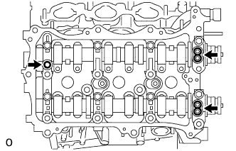
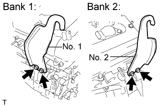
INSTALL CYLINDER HEAD COVER SUB-ASSEMBLY (for Bank 2)
-
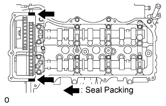
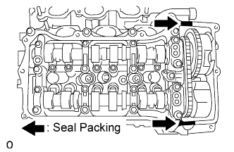
Apply seal packing as shown in the illustration.
Seal packing Toyota Genuine Seal Packing Black, Three Bond 1207B or equivalent Note
-
Remove any oil from the contact surfaces.
-
Install the cylinder head cover sub-assembly within 3 minutes after applying seal packing.
-
Do not start the engine for at least 2 hours after installing.
-
-
Install 3 new gaskets as shown in the illustration.
-
Install a new cylinder head cover gasket to the cylinder head cover sub-assembly.
-
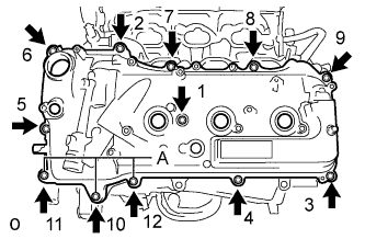
Install the cylinder head cover sub-assembly with the 12 bolts and a new seal washer.
- Torque:
- Bolts A
- 21 N*m { 214 kgf*cm, 15 ft.*lbf }
- Except bolts A
- 10 N*m { 102 kgf*cm, 7 ft.*lbf }
Tech Tips
After tightening all bolts, check the tightening torque of 1 and 10. Retighten the bolt if necessary.
-
-
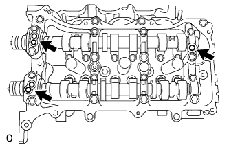
INSTALL CYLINDER HEAD COVER SUB-ASSEMBLY (for Bank 1)
-
Apply seal packing as shown in the illustration.
Seal packing Toyota Genuine Seal Packing Black, Three Bond 1207B or equivalent Note
-
Remove any oil from the contact surface.
-
Install the head cover within 3 minutes after applying seal packing.
-
Do not start the engine for at least 2 hours after installing.
-
-
Install 3 new gaskets as shown in the illustration.
-
Install a new cylinder head cover gasket to the cylinder head cover sub-assembly.
-
Install a head cover with the 12 bolts and a new seal washer.
- Torque:
- Bolts A
- 21 N*m { 214 kgf*cm, 15 ft.*lbf }
- Except bolts A
- 10 N*m { 102 kgf*cm, 7 ft.*lbf }
Tech Tips
After tightening all bolts, check the tightening torque of 1 and 11. Retighten the bolt if necessary.
-
-
INSTALL WATER INLET HOUSING
-
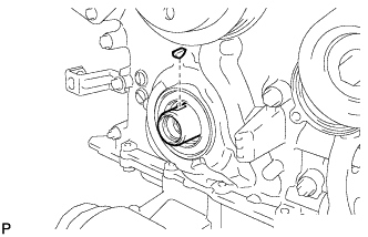
Install 2 new O-rings.
Tech Tips
Apply a small amount of water or soapy water to O-ring (A) shown in the illustration before installation.
-
Install the 2 stud bolts.
- Torque:
- 4.0 N*m { 41 kgf*cm, 35 in.*lbf }
-
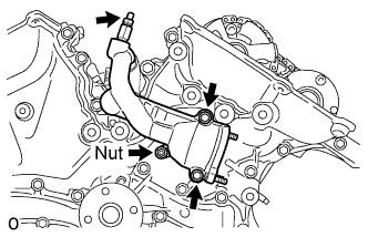
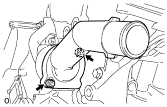
Install the water inlet housing with the 2 bolts and nut.
- Torque:
- 10 N*m { 102 kgf*cm, 7 ft.*lbf }
Note
Be careful that the O-ring does not get caught between the parts.
-
Connect the No. 1 water by-pass hose.
-
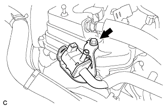
Apply adhesive around the drain cock.
Adhesive Toyota Genuine Adhesive 1324, Three Bond 1324 or equivalent -
Install the drain cock assembly to the water inlet housing.
- Torque:
- 30 N*m { 306 kgf*cm, 22 ft.*lbf }
-
Install the drain cock plug to the drain cock assembly.
- Torque:
- 13 N*m { 130 kgf*cm, 9 ft.*lbf }
-
Install a new gasket to the thermostat.
-
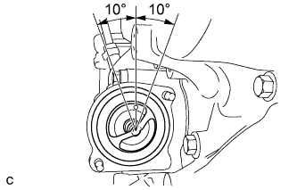
Align the thermostat jiggle valve with the upper stud bolt, and insert the thermostat in the water inlet housing.
Tech Tips
The jiggle valve may be set within 10° of either side of the prescribed position.
-
Install the water inlet with the 2 nuts.
- Torque:
- 10 N*m { 102 kgf*cm, 7 ft.*lbf }
-
-
INSTALL CRANKSHAFT PULLEY
-
Align the pulley set key with the key groove of the pulley, and slide on the pulley.
-
Using SST, install the pulley bolt.
- SST
- 09213-70011 ( 09213-70020 )
- 09330-00021
- Torque:
- 250 N*m { 2550 kgf*cm, 184 ft.*lbf }
-
-
INSTALL OIL PIPE
-
Make sure that there is no foreign matter on the mesh of the oil control valve filter RH.
Note
Do not touch the mesh when installing the oil control valve filter.
-
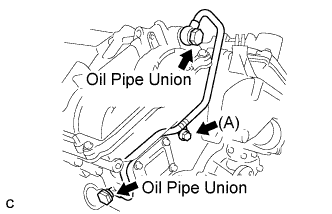
Install a new gasket and temporarily install the oil pipe (on the cylinder head side) with the oil check valve bolt.
-
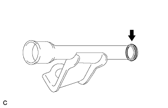
Install the oil control valve filter RH to the oil pipe union. Install new gaskets and temporarily install the oil pipe (on the head cover side).
-
Tighten the oil pipe union (on the cylinder head side).
- Torque:
- 65 N*m { 663 kgf*cm, 48 ft.*lbf }
Note
If the link that connects the gaskets is broken, remove the connecting link by using side cutters or a similar tool.
-
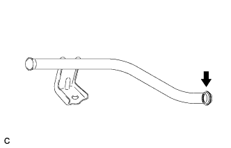
Tighten the oil pipe union (on the head cover side).
- Torque:
- 65 N*m { 663 kgf*cm, 48 ft.*lbf }
-
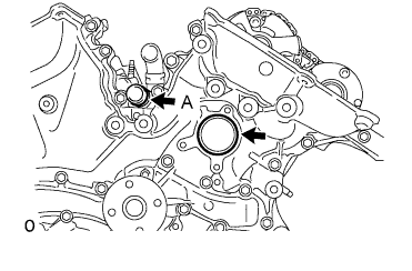
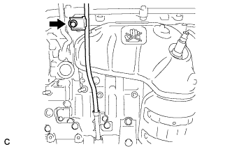
Install the bolt (A) to the cylinder head.
- Torque:
- 10 N*m { 102 kgf*cm, 7 ft.*lbf }
-
-
INSTALL NO. 1 OIL PIPE
-
Make sure that there is no foreign matter on the mesh of the oil control valve filter LH.
Note
Do not touch the mesh when installing the oil control valve filter.
-
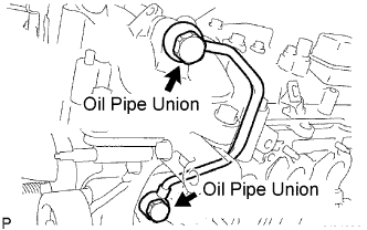
Install a new gasket and temporarily install the oil pipe (on the cylinder head side) with the oil check valve bolt.
-
Install the oil control valve filter LH to the oil pipe union. Install new gaskets and temporarily install the oil pipe (on the head cover side).
-
Tighten the oil pipe union (on the cylinder head side).
- Torque:
- 65 N*m { 663 kgf*cm, 48 ft.*lbf }
Note
If the link that connects the gaskets is broken, remove the connecting link by using side cutters or a similar tool.
-
Tighten the oil pipe union (on the head cover side).
- Torque:
- 65 N*m { 663 kgf*cm, 48 ft.*lbf }
-
-
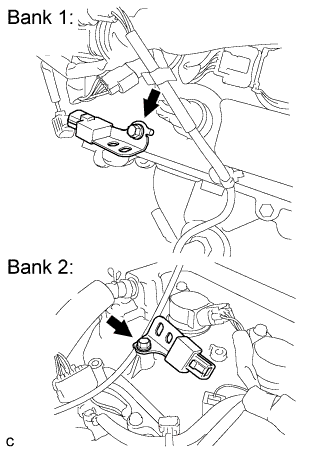
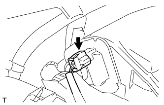
INSTALL CRANKSHAFT POSITION SENSOR
-
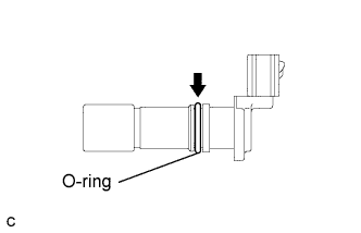
Apply a light coat of engine oil to the O-ring on the crank position sensor.
-
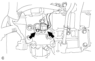
Install the crank position sensor with the bolt.
- Torque:
- 10 N*m { 102 kgf*cm, 7 ft.*lbf }
-
Connect the crank position sensor connector.
-
-
INSTALL NO. 1 VACUUM SWITCHING VALVE ASSEMBLY
-
Install the bolt and No. 1 vacuum switching valve.
- Torque:
- 10 N*m { 102 kgf*cm, 7 ft.*lbf }
-
-
INSTALL RADIO SETTING CONDENSER
-
Install the 2 bolts and 2 radio setting condensers.
- Torque:
- 10 N*m { 102 kgf*cm, 7 ft.*lbf }
-
-
INSTALL NO. 1 FRONT ENGINE MOUNTING BRACKET LH
-
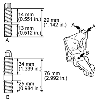
When replacing 2 stud bolts, install them by using an E8 "TORX" socket wrench.
- Torque:
- Bolt A
- 10 N*m { 102 kgf*cm, 7 ft.*lbf }
-
When replacing the stud bolt, install it by using a 8mm socket wrench.
- Torque:
- Bolt B
- 10 N*m { 102 kgf*cm, 7 ft.*lbf }
-
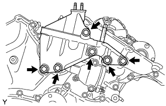
Install the No. 1 front engine mounting bracket LH with the 6 bolts.
- Torque:
- 54 N*m { 550 kgf*cm, 40 ft.*lbf }
Note
-
Install the water inlet and mounting bracket within 15 minutes after installing the chain cover.
-
Do not start the engine for at least 2 hours after installation.
-
-
INSTALL NO. 2 IDLER PULLEY SUB-ASSEMBLY
-
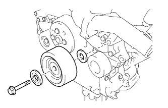
Install the idler pulley cover plate, No. 2 idler pulley sub-assembly and No. 2 idler pulley cover plate with the bolt.
- Torque:
- 54 N*m { 550 kgf*cm, 40 ft.*lbf }
-
-
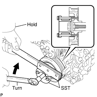
INSTALL WATER PUMP PULLEY
-
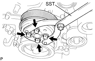
Temporarily install the water pump pulley with the 4 bolts.
-
Using SST, hold the water pump pulley.
- SST
- 09960-10010 ( 09962-01000, 09963-00700 )
-
Tighten the 4 bolts.
- Torque:
- 21 N*m { 214 kgf*cm, 15 ft.*lbf }
-
-
INSTALL NO. 2 TIMING GEAR COVER
-
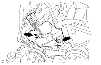
Install the No. 2 timing gear cover with the 2 bolts.
- Torque:
- 6.0 N*m { 61 kgf*cm, 53 in.*lbf }
-
-
INSTALL V-RIBBED BELT TENSIONER ASSEMBLY
-
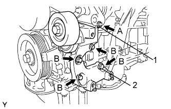
Temporarily install the V-ribbed belt tensioner assembly with the 5 bolts.
Tech Tips
Each bolt length is as follows:
A: 70 mm (2.76 in.)
B: 33 mm (1.30 in.)
-
Install the V-ribbed belt tensioner assembly by tightening the bolt 1 and bolt 2 in the order shown in the illustration.
- Torque:
- 43 N*m { 438 kgf*cm, 32 ft.*lbf }
-
Tighten the other bolts.
- Torque:
- 43 N*m { 438 kgf*cm, 32 ft.*lbf }
-
-
INSTALL EXHAUST MANIFOLD SUB-ASSEMBLY LH
-
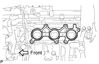
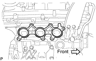
Install a new gasket as shown in the illustration.
-
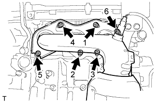
Install the exhaust manifold sub-assembly LH with the 6 nuts in the order shown in the illustration.
- Torque:
- 21 N*m { 214 kgf*cm, 15 ft.*lbf }
-
-
INSTALL NO. 2 EXHAUST MANIFOLD HEAT INSULATOR
-
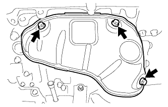
Install the No. 2 exhaust manifold heat insulator with the 3 bolts.
- Torque:
- 8.5 N*m { 87 kgf*cm, 75 in.*lbf }
-
-
INSTALL NO. 2 MANIFOLD STAY
-
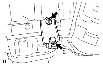
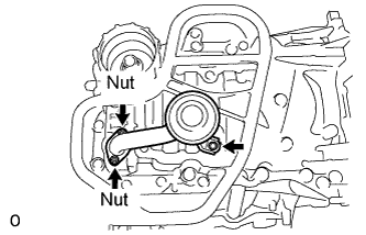
Install the No. 2 manifold stay by tightening the bolt and nut in the order shown in the illustration.
- Torque:
- 34 N*m { 347 kgf*cm, 25 ft.*lbf }
-
-
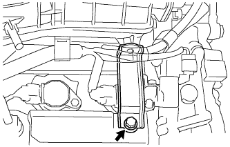
INSTALL ENGINE OIL LEVEL DIPSTICK GUIDE
-
Apply a light coat of engine oil to a new O-ring and install it to the engine oil level dipstick guide.
-

Install the bolt and engine oil level dipstick guide.
- Torque:
- 21 N*m { 214 kgf*cm, 15 ft.*lbf }
-
-
INSTALL NO. 2 ENGINE OIL LEVEL DIPSTICK GUIDE
-
Install a new O-ring to the No. 2 engine oil level dipstick guide.
-
Apply a light coat of engine oil to the O-ring.
-
Push in the No. 2 engine oil level dipstick guide end into the No. 1 engine oil level dipstick guide.
-
Install the No. 2 engine oil level dipstick guide with the bolt.
- Torque:
- 21 N*m { 214 kgf*cm, 15 ft.*lbf }
-
Install the engine oil level dipstick.
-
-
INSTALL EXHAUST MANIFOLD SUB-ASSEMBLY RH
-
Install a new gasket as shown in the illustration.
-
Install the exhaust manifold sub-assembly RH with the 6 nuts in the order shown in the illustration.
- Torque:
- 21 N*m { 214 kgf*cm, 15 ft.*lbf }
-
-
INSTALL IGNITION COIL ASSEMBLY
-
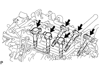
Install the 6 ignition coils with the 6 bolts.
- Torque:
- 10 N*m { 102 kgf*cm, 7 ft.*lbf }
-
Connect the 6 ignition coil connectors.
-
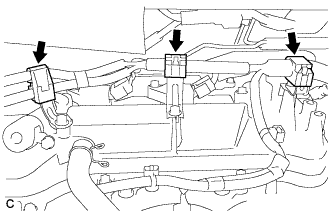
Connect the 3 wire harness clamps.
-
-
INSTALL THROTTLE BODY BRACKET
-
Install the throttle body bracket with the bolt.
- Torque:
- 21 N*m { 214 kgf*cm, 15 ft.*lbf }
-
-
INSTALL NO. 1 SURGE TANK STAY
-
Install the No. 1 surge tank stay with the bolt.
- Torque:
- 21 N*m { 214 kgf*cm, 15 ft.*lbf }
-
-
INSTALL INTAKE AIR SURGE TANK ASSEMBLY
NOTICE DO NOT apply oil to the bolts listed below: Tightening Part Surge Tank and Intake Manifold No. 1 Surge Tank Stay and Surge Tank Throttle Body Bracket and Surge Tank
-
Install 3 new air surge tank to intake manifold gaskets to the intake air surge tank.
-

Using a 5 mm hexagon socket wrench, install the intake air surge tank assembly with the 4 bolts and 2 nuts.
- Torque:
- Bolt
- 18 N*m { 184 kgf*cm, 13 ft.*lbf }
- Nut
- 16 N*m { 163 kgf*cm, 12 ft.*lbf }
-
Install the throttle body bracket and No. 1 surge tank stay with the 2 bolts.
- Torque:
- 21 N*m { 214 kgf*cm, 15 ft.*lbf }
-
Connect the connector to the intake air control valve assembly.
-
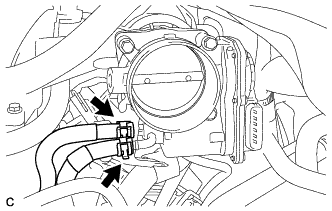
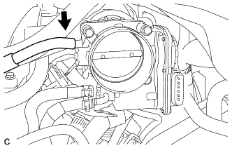
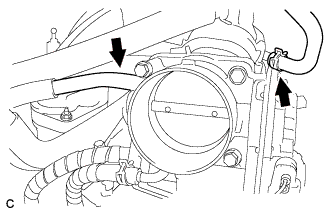
Connect the 2 water by-pass hoses to the throttle body assembly.
-
Connect the fuel vapor feed hose to the intake air surge tank assembly.
-
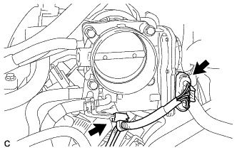
Connect the throttle body assembly connector and wire harness clamp to the throttle body assembly.
-
Connect the ventilation hose.
-
Connect the union to connector tube hose.
-
-
INSTALL ENGINE HANGER
-
Install the 2 engine hangers with the 4 bolts as shown in the illustration.
Part No. No. 1 Engine hanger 12281-31120 No. 2 Engine hanger 12282-31100 Bolts 91671-10825 - Torque:
- 33 N*m { 337 kgf*cm, 24 ft.*lbf }
-
Attach the engine sling device and hang the engine with the chain block.
-
-
REMOVE ENGINE FROM ENGINE STAND
-
INSTALL AUTOMATIC TRANSAXLE ASSEMBLY
Tech Tips
See the steps from "Install Automatic Transaxle Assembly" through "Install Engine Assembly with Transaxle" Click here.