- Click here
INSPECT OIL PUMP RELIEF VALVE
-
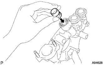
Coat the relief valve with engine oil and check that it falls smoothly into the valve hole under its own weight.
If the valve does not fall smoothly, replace the relief valve. If necessary, replace the oil pump assembly.
-
- Click here
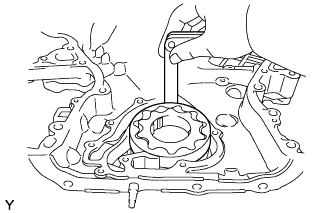
INSPECT OIL PUMP ROTOR SET
-
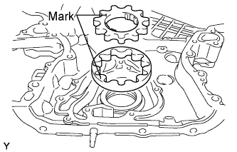
Install the rotors to the timing chain cover with the rotors' marks facing outward. Check that the rotors rotate smoothly.
-
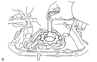
Check the tip clearance.
-
Using a feeler gauge, measure the clearance between the drive and driven rotors, as shown in the illustration.
Tip Clearance Standard Maximum 0.060 to 0.160 mm (0.0024 to 0.0063 in.) 0.160 mm (0.0063 in.) If the clearance is greater than the maximum, replace the drive and driven rotors.
-
-
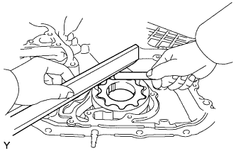
Check the side clearance.
-
Using a feeler gauge and precision straightedge, measure the clearance between the rotors and precision straightedge, as shown in the illustration.
Side Clearance Standard Maximum 0.030 to 0.090 mm (0.0012 to 0.0035 in.) 0.090 mm (0.0035 in.) If the side clearance is greater than the maximum, replace the timing chain cover.
-
-
Check the body clearance.
-
Using a feeler gauge, measure the clearance between the timing chain cover and driven rotor, as shown in the illustration.
Body Clearance Standard Maximum 0.250 to 0.325 mm (0.0098 to 0.0128 in.) 0.325 mm (0.0128 in.) If the body clearance is greater than the maximum, replace the timing chain cover.
-
-