- Click here
REMOVE AUTOMATIC TRANSAXLE ASSEMBLY
Tip:See the steps from "Remove Engine Assembly with Transaxle" through "Remove Automatic Transaxle Assembly" (Click here).
- Click here
INSTALL ENGINE ON ENGINE STAND
-
Install the engine onto an engine stand with the bolts.
-
- Click here
REMOVE ENGINE HANGER
-
Remove the 4 bolts and 2 engine hangers.
-
- Click here
REMOVE INTAKE AIR SURGE TANK ASSEMBLY
-
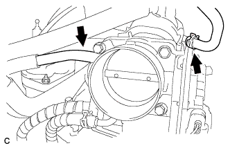
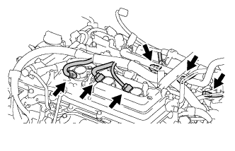
Disconnect the union to connector tube hose.
-
Disconnect the ventilation hose.
-
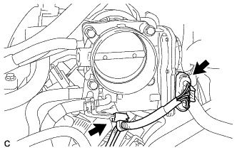
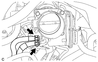
Disconnect the throttle body assembly connector and wire harness clamp.
-
Disconnect the fuel vapor feed hose.
-
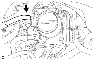
Disconnect the 2 water by-pass hoses.
-
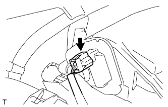
Disconnect the connector from the intake air control valve assembly.
-
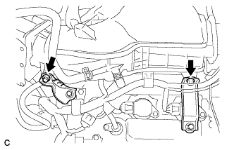
Remove the bolt and separate the No. 1 surge tank stay from the intake air surge tank assembly.
-
Remove the bolt and separate the throttle body bracket from the intake air surge tank assembly.
-

Remove the 2 nuts from the intake air surge tank assembly.
-
Using a 5 mm socket hexagon wrench, remove the 4 bolts.
-
Remove the intake air surge tank assembly and 3 air surge tank to intake manifold gaskets.
-
- Click here
REMOVE NO. 1 SURGE TANK STAY
-
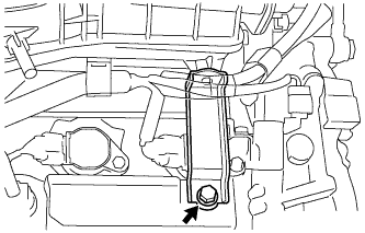
Remove the bolt and No. 1 surge tank stay.
-
- Click here
REMOVE THROTTLE BODY BRACKET
-
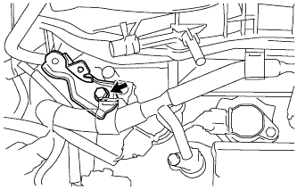
Remove the bolt and throttle body bracket.
-
- Click here
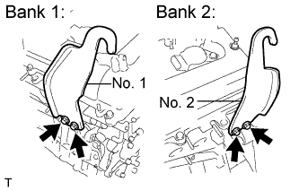
REMOVE IGNITION COIL ASSEMBLY
-
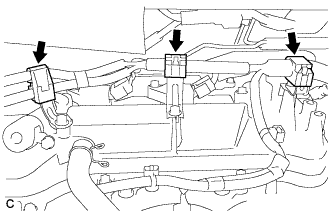
Disconnect the 3 wire harness clamps.
-
Disconnect the 6 ignition coil connectors.
-
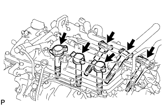
Remove the 6 bolts and 6 ignition coils.
-
- Click here
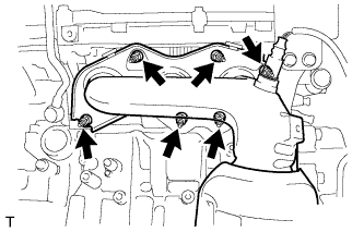
REMOVE EXHAUST MANIFOLD SUB-ASSEMBLY RH
-
Uniformly loosen and remove the 6 nuts.
-
Remove the exhaust manifold sub-assembly and gasket.
-
- Click here
REMOVE NO. 2 ENGINE OIL LEVEL DIPSTICK GUIDE
-
Remove the oil level dipstick.
-
Remove the bolt and No. 2 engine oil level dipstick guide.
-
Remove the O-rings from the No. 2 engine oil level dipstick guide.
-
- Click here
REMOVE ENGINE OIL LEVEL DIPSTICK GUIDE
-

Remove the bolt and engine oil level dipstick guide.
-
Remove the O-ring.
-
- Click here
REMOVE NO. 2 MANIFOLD STAY
-
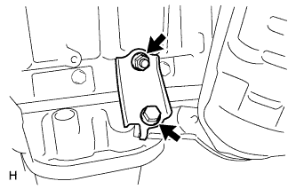
Remove the bolt, nut and No. 2 manifold stay.
-
- Click here
REMOVE NO. 2 EXHAUST MANIFOLD HEAT INSULATOR
-
Remove the 3 bolts and No. 2 exhaust manifold heat insulator.
-
- Click here
REMOVE EXHAUST MANIFOLD SUB-ASSEMBLY LH
-
Uniformly loosen and remove the 6 nuts.
-
Remove the exhaust manifold assembly and gasket.
-
- Click here
REMOVE V-RIBBED BELT TENSIONER ASSEMBLY
-
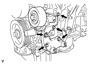
Remove the 5 bolts and V-ribbed belt tensioner assembly.
-
- Click here
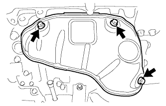
REMOVE NO. 2 TIMING GEAR COVER
-
Remove the 2 bolts and No. 2 timing gear cover.
-
- Click here
REMOVE WATER PUMP PULLEY
-
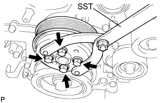
Using SST, hold the water pump pulley.
09960-10010 09962-01000 09963-00700 -
Remove the 4 bolts and water pump pulley.
-
- Click here
REMOVE NO. 2 IDLER PULLEY SUB-ASSEMBLY
-
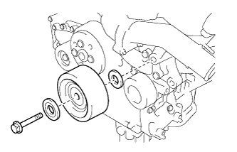
Remove the bolt, No. 2 idler pulley cover plate, No. 2 idler pulley sub-assembly and idler pulley cover plate.
-
- Click here
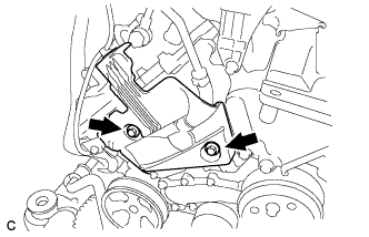
REMOVE NO. 1 FRONT ENGINE MOUNTING BRACKET LH
-
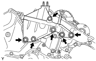
Remove the 6 bolts and No. 1 front engine mounting bracket LH.
-
Using a "TORX" socket wrench E8, remove the 2 stud bolts.
-
Using a socket wrench 8mm, remove the stud bolt.
-
- Click here
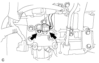
REMOVE RADIO SETTING CONDENSER
-
Remove the 2 bolts and 2 radio setting condensers.
-
- Click here
REMOVE NO. 1 VACUUM SWITCHING VALVE ASSEMBLY
-
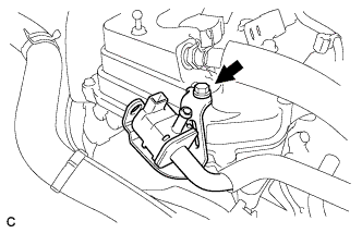
Remove the bolt and No. 1 vacuum switching valve.
-
- Click here
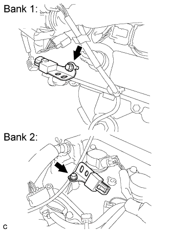
REMOVE CRANKSHAFT POSITION SENSOR
-
Disconnect the crank position sensor connector.
-
Remove the bolt and crank position sensor.
-
- Click here
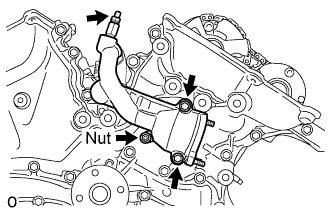
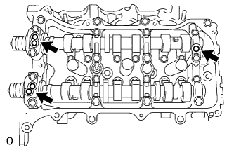
REMOVE NO. 1 OIL PIPE
-
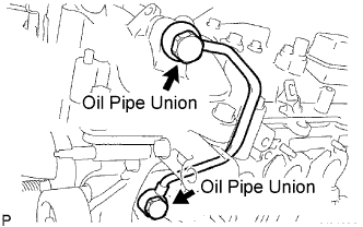
Remove the 2 oil pipe unions, gaskets and No. 1 oil pipe.
-
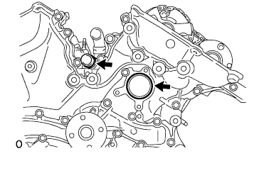
Remove the oil control valve filter LH and gaskets.
-
- Click here
REMOVE OIL PIPE
-
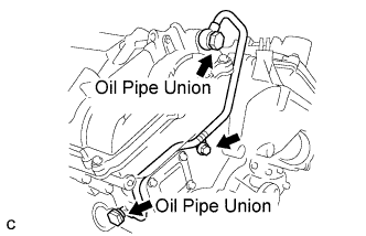
Remove the bolt.
-
Remove the 2 oil pipe unions and oil pipe.
-
Remove the oil control valve filter RH and gaskets.
-
- Click here
REMOVE CRANKSHAFT PULLEY
-
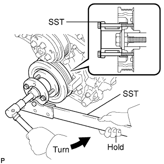
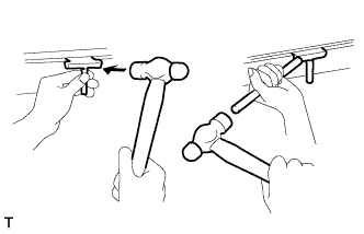
Using SST, loosen the crankshaft pulley bolt.
09213-70011 09213-70020 09330-00021 -
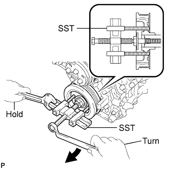
Using SST, remove the crankshaft pulley bolt and crankshaft pulley.
09950-50013 09951-05010 09952-05010 09953-05020 09954-05021 -
Remove the pulley set key from the crankshaft.
-
- Click here
REMOVE WATER INLET HOUSING
-
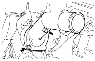
Remove the 2 nuts, water inlet and thermostat.
-
Remove the gasket.
-
Remove the 2 stud bolts.
-
Separate the No. 1 water by-pass hose from the water inlet housing.
-
Remove the drain cock plug.
-
Remove the drain cock assembly.
-
Remove the 2 bolts, nut, and water inlet housing.
-
Remove the 2 O-rings.
-
- Click here
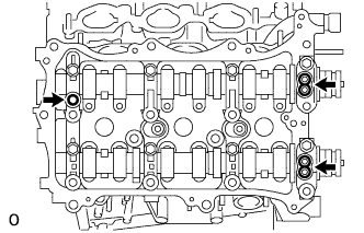
REMOVE CYLINDER HEAD COVER SUB-ASSEMBLY (for Bank 1)
-
Remove the 12 bolts, seal washer, cylinder head cover sub-assembly and cylinder head cover gasket.
-
Remove the 3 gaskets.
-
- Click here
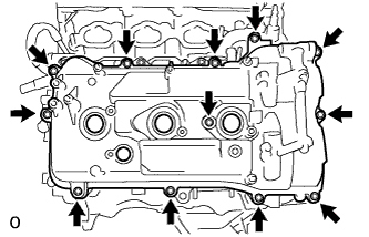
REMOVE CYLINDER HEAD COVER SUB-ASSEMBLY (for Bank 2)
-
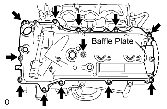
Remove the 12 bolts, seal washer, cylinder head cover sub-assembly and cylinder head cover gasket.
Note:The baffle plate is located on the back of the portion shown in the illustration. Do not damage the baffle plate when removing the cylinder head cover sub-assembly.
-
Remove the 3 gaskets.
-
- Click here
REMOVE NO. 2 OIL PAN SUB-ASSEMBLY
-
Remove the 16 bolts and 2 nuts.
-
Insert the blade of the oil pan seal cutter between the oil pans. Cut through the applied sealer and remove the No. 2 oil pan sub-assembly.
Note:Be careful not to damage the contact surfaces of the oil pans.
-
Using a "TORX" socket wrench E6, remove the 2 stud bolts.
-
- Click here
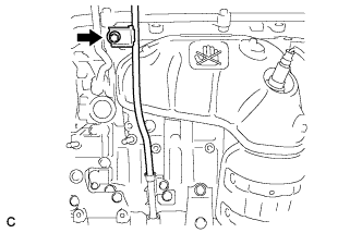
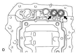
REMOVE OIL STRAINER SUB-ASSEMBLY
-
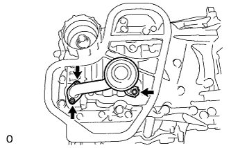
Remove the bolt, 2 nuts, oil strainer sub-assembly and gasket.
-
Using a "TORX" socket wrench E6, remove the 2 stud bolts.
-
- Click here
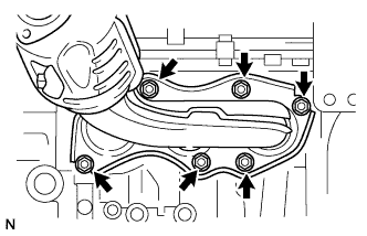
REMOVE OIL PAN SUB-ASSEMBLY
-
Remove the 16 bolts and 2 nuts.
Tip:Be sure to clean the bolts and stud bolts and check the threads for cracks or other damage.
-
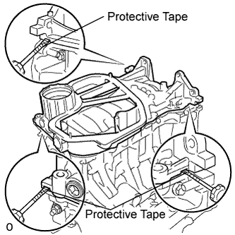
Remove the oil pan sub-assembly by prying between the oil pan sub-assembly and cylinder block sub-assembly with a screwdriver.
Note:Be careful not to damage the contact surfaces of the cylinder block and oil pan.
Tip:Tape the screwdriver tip before use.
-
Remove the 2 O-rings.
-
Using a "TORX" socket wrench E8, remove the 2 stud bolts.
-
- Click here
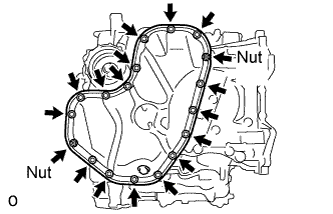
REMOVE TIMING CHAIN COVER SUB-ASSEMBLY
-
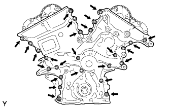
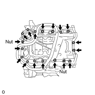
Remove the 23 bolts and 2 nuts as shown in the illustration.
-
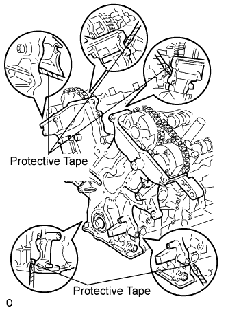
Remove the timing chain cover by prying between the timing chain cover and cylinder head or cylinder block with a screwdriver.
Note:Be careful not to damage the contact surfaces of the cylinder head, cylinder block and chain cover.
Tip:Tape the screwdriver tip before use.
-
Remove the gasket.
-
- Click here
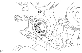
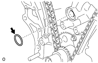
REMOVE TIMING CHAIN CASE OIL SEAL
-
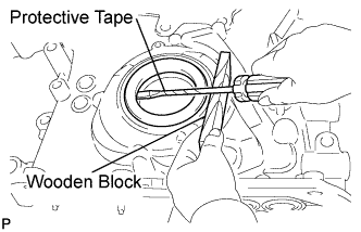
Using a screwdriver, pry out the oil seal.
Tip:Tape the screwdriver tip before use.
-