CRUISE CONTROL SYSTEM Cruise Main Indicator Light Circuit
DESCRIPTION
-
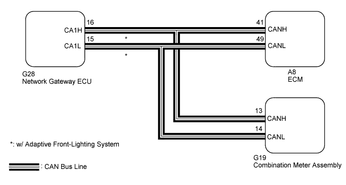
The ECM detects a cruise control main switch signal and sends it to the combination meter assembly through CAN. Then the cruise main indicator light comes on.
-
The cruise main indicator light circuit uses CAN for communication. If there is a malfunction in this circuit, check for DTCs in the CAN communication system before troubleshooting this circuit.
WIRING DIAGRAM
INSPECTION PROCEDURE
PROCEDURE
-
PERFORM ACTIVE TEST USING INTELLIGENT TESTER
-
Connect the intelligent tester to the DLC3.
-
Turn the engine switch on (IG).
-
Turn the tester on.
-
Enter the following menus: Body / Combination Meter / Active Test.
-
Check the cruise main indicator light by performing the Active Test.
Combination Meter Tester Display Test Part Control Range Diagnostic Note Indicat. Lamp Cruise Cruise main indicator light OFF or ON Confirm that the vehicle is stopped with the engine idling OK The cruise main indicator light blinks or goes off according to tester operation.
NG 
REPLACE COMBINATION METER ASSEMBLY Click here
OK 
-
-
READ VALUE USING INTELLIGENT TESTER
-
Connect the intelligent tester to the DLC3.
-
Turn the engine switch on (IG).
-
Turn the tester on.
-
Enter the following menus: Powertrain / Cruise Control / Data List.
-
Check the Data List for proper functioning of the cruise main indicator light.
Cruise Control Tester Display Measurement Item/Range Normal Condition Diagnostic Note CCS Indicator M-CPU Cruise main indicator signal (Main CPU)/ON or OFF ON: "Cruise" on
OFF: "Cruise" off
- OK The display changes as shown above according to cruise control main switch operation. Result Result Proceed to OK A NG (for 2GR-FE) B NG (for 2AZ-FE) C
B
REPLACE ECM (for 2GR-FE) Click here
C
REPLACE ECM (for 2AZ-FE) Click here
A 
PROCEED TO NEXT SUSPECTED AREA SHOWN IN PROBLEM SYMPTOMS TABLE Click here
-