- Click here
INSTALL WATER PUMP ASSEMBLY
-
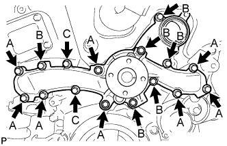
Install a new water pump gasket and the water pump assembly with the 16 bolts.
Bolt A 21 N*m 214 kgf*cm 15 ft.*lbf Bolts B and C 11 N*m 112 kgf*cm 8 ft.*lbf Note:
-
Make sure that there is no oil on the threads of bolts A.
-
Be sure to replace 2 bolts C with new ones or reuse them after applying adhesive 1344.
Adhesive Toyota Genuine Adhesive 1344, Three Bond 1344 or equivalent
-
-
- Click here
INSTALL WATER PUMP PULLEY
-
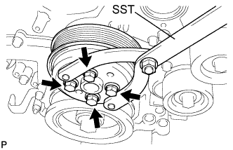
Temporarily install the water pump pulley with the 4 bolts.
-
Using SST, hold the water pump pulley.
09960-10010 09962-01000 09963-00700 -
Tighten the 4 bolts.
21 N*m 214 kgf*cm 15 ft.*lbf
-
- Click here
INSTALL WATER INLET HOUSING
-
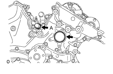
Install 2 new O-rings.
Tip:Apply a small amount of water or soapy water to O-ring (A) shown in the illustration before installation.
-
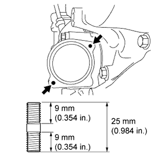
Install the 2 stud bolts.
4.0 N*m 41 kgf*cm 35 in.*lbf -
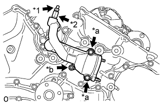
Install the water inlet housing with the 2 bolts and nut.
Table 1. Text in Illustration *1 Drain Cock Plug *2 Drain Cock Assembly *a Bolt *b Nut 10 N*m 102 kgf*cm 7 ft.*lbf Note:Be careful that the O-ring does not get caught between the parts.
-
Connect the No. 1 water by-pass hose to the water inlet housing.
-
Apply adhesive around the drain cock assembly.
Adhesive Toyota Genuine Adhesive 1324, Three Bond 1324 or equivalent -
Install the drain cock assembly to the water inlet housing.
30 N*m 306 kgf*cm 22 ft.*lbf -
Install the drain cock plug to the drain cock assembly.
13 N*m 130 kgf*cm 9 ft.*lbf -
Install a new gasket to the thermostat.
-
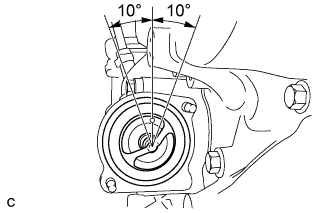
Align the thermostat jiggle valve with the upper stud bolt, and insert the thermostat in the water inlet housing.
Tip:The jiggle valve may be set within 10° of either side of the prescribed position.
-
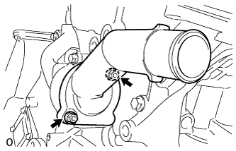
Install the water inlet with the 2 nuts.
10 N*m 102 kgf*cm 7 ft.*lbf
-
- Click here
INSTALL V-RIBBED BELT TENSIONER ASSEMBLY
-
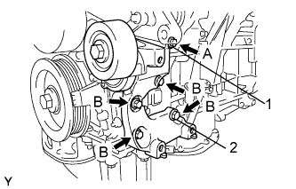
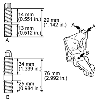
Temporarily install the V-ribbed belt tensioner assembly with the 5 bolts.
Tip:Each bolt length is as follows:
A: 70 mm (2.76 in.)
B: 33 mm (1.30 in.)
-
Install the V-ribbed belt tensioner assembly by tightening the bolt 1 and bolt 2 in the order shown in the illustration.
43 N*m 438 kgf*cm 32 ft.*lbf -
Tighten the other bolts.
43 N*m 438 kgf*cm 32 ft.*lbf
-
- Click here
INSTALL NO. 2 IDLER PULLEY SUB-ASSEMBLY
-
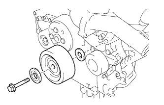
Install the idler pulley cover plate, No. 2 idler pulley sub-assembly and No. 2 idler pulley cover plate with the bolt.
54 N*m 550 kgf*cm 40 ft.*lbf
-
- Click here
INSTALL FRONT NO. 1 ENGINE MOUNTING BRACKET LH
-
Using an E8 "TORX" socket wrench, install the 2 stud bolts.
Bolt A 10 N*m 102 kgf*cm 7 ft.*lbf -
Using an 8 mm socket wrench, install the 2 stud bolts.
Bolt B 10 N*m 102 kgf*cm 7 ft.*lbf -
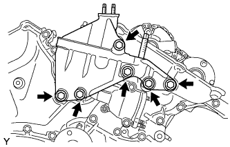
Install the No. 1 front engine mounting bracket LH with the 6 bolts.
54 N*m 550 kgf*cm 40 ft.*lbf Note:
-
Install the water inlet and No. 1 front engine mounting bracket LH within 15 minutes after installing the timing chain cover assembly.
-
Do not start the engine for at least 2 hours after installation.
-
-
- Click here
INSTALL ENGINE HANGER
-
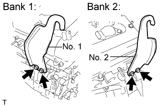
Install the 2 engine hangers with the 4 bolts as shown in the illustration.
Part No. No. 1 Engine hanger 12281-31120 No. 2 Engine hanger 12282-31100 Bolts 91671-10825 33 N*m 337 kgf*cm 24 ft.*lbf -
Attach the engine sling device and hang the engine with the chain block.
-
- Click here
REMOVE ENGINE ON ENGINE STAND
- Click here
INSTALL AUTOMATIC TRANSAXLE ASSEMBLY
Tip:See the steps from "Install Automatic Transaxle Assembly" through "Install Engine Assembly with Transaxle" (Click here).