COOLING FAN SYSTEM Cooling Fan Circuit
DESCRIPTION
The ECM calculates an appropriate cooling fan speed based on the engine coolant temperature, air conditioning switch condition, refrigerant pressure, engine speed and vehicle speed, and sends the signals to the cooling fan ECUs to regulate the cooling fans. The cooling fan ECUs control each cooling fan speed based on the duty ratio signal sent from the ECM. By basing its control on the operating conditions, the ECM can control the fan speed optimally using the cooling fan ECUs, achieving both high cooling performance and quietness.
WIRING DIAGRAM
Refer to System Diagram Click here.
INSPECTION PROCEDURE
PROCEDURE
-
PERFORM ACTIVE TEST USING INTELLIGENT TESTER (CONTROL THE ELECTRIC COOLING FAN)
-
Connect the intelligent tester to the DLC3.
-
Turn the engine switch on (IG) and turn the tester on.
-
Enter the following menus: Powertrain / Engine / Active Test / Control the Electric Cooling Fan.
-
Check operation of the cooling fan while operating it using the intelligent tester.
OK Tester Operation Fan Operation ON Cooling fan operates OFF Cooling fan stops Result Result Proceed to OK A NG (Main fan) B NG (Sub fan) C NG (Main and sub fans) D
B 
INSPECT COOLING FAN SYSTEM (FOR MAIN FAN) Click here
C
INSPECT COOLING FAN SYSTEM (FOR SUB FAN) Click here
D
INSPECT COOLING FAN SYSTEM (FOR MAIN AND SUB FANS) Click here
A 
PROCEED TO NEXT SUSPECTED AREA SHOWN IN PROBLEM SYMPTOMS TABLE Click here
-
-
INSPECT COOLING FAN SYSTEM (FOR MAIN FAN)
-
Disconnect the A8 ECM connector.
-
Turn the engine switch on (IG).
-
Check the operation of the cooling fan (main fan).
OK The cooling fan (main fan) operates. -
Reconnect the A8 ECM connector.
NG
CHECK HARNESS AND CONNECTOR (COOLING FAN ECU (FOR MAIN FAN) - ECM) Click here
OK 
-
-
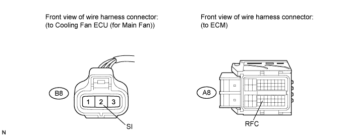
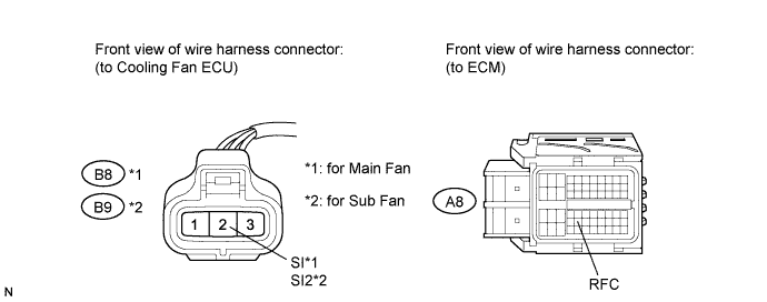
CHECK HARNESS AND CONNECTOR (COOLING FAN ECU (FOR MAIN FAN) - ECM)
-
Disconnect the cooling fan ECU connector.
-
Disconnect the ECM connector.
-
Measure the resistance according to the value(s) in the table below.
Standard Resistance Tester Connection Condition Specified Condition B8-2 (SI) - A8-43 (RFC) Always Below 1 Ω -
Reconnect the ECM connector.
-
Reconnect the cooling fan ECU connector.
NG 
REPAIR OR REPLACE HARNESS OR CONNECTOR
OK
REPLACE COOLING FAN ECU (FOR MAIN FAN)
-
-
CHECK HARNESS AND CONNECTOR (COOLING FAN ECU (FOR MAIN FAN) - ECM)
-
Disconnect the cooling fan ECU connector.
-
Disconnect the ECM connector.
-
Measure the resistance according to the value(s) in the table below.
Standard Resistance Tester Connection Condition Specified Condition B8-2 (SI) or A8-43 (RFC) - Body ground Always 10 kΩ or higher -
Reconnect the ECM connector.
-
Reconnect the cooling fan ECU connector.
NG
REPAIR OR REPLACE HARNESS OR CONNECTOR
OK
-
-
INSPECT COOLING FAN MOTOR (FOR MAIN FAN)
-
Inspect the cooling fan motor Click here.
NG
REPLACE COOLING FAN MOTOR (FOR MAIN FAN) Click here
OK
-
-
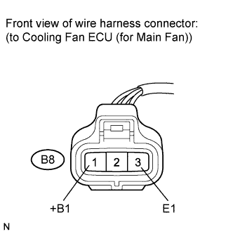
CHECK COOLING FAN ECU POWER SOURCE CIRCUIT (FOR MAIN FAN)
-
Disconnect the cooling fan ECU connector.
-
Turn the engine switch on (IG).
-
Measure the voltage according to the value(s) in the table below.
Standard Voltage Tester Connection Switch Condition Specified Condition B8-1 (+B1) - B8-3 (E1) Engine switch on (IG) 11 to 14 V -
Reconnect the cooling fan ECU connector.
NG
CHECK HARNESS OR CONNECTOR (COOLING FAN ECU (FOR MAIN FAN) - BODY GROUND) Click here
OK
REPLACE COOLING FAN ECU (FOR MAIN FAN)
-
-
CHECK HARNESS OR CONNECTOR (COOLING FAN ECU (FOR MAIN FAN) - BODY GROUND)
-
Disconnect the cooling fan ECU connector.
-
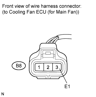
Measure the resistance according to the value(s) in the table below.
Standard Resistance Tester Connection Condition Specified Condition B8-3 (E1) - Body ground Always Below 1 Ω -
Reconnect the cooling fan ECU connector.
NG
REPAIR OR REPLACE HARNESS OR CONNECTOR
OK
-
-
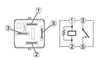
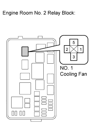
INSPECT NO. 1 COOLING FAN RELAY
-
Remove the NO. 1 cooling fan relay from the engine room No. 2 relay block.
-
Measure the resistance according to the value(s) in the table below.
Standard Resistance Tester Connection Condition Specified Condition 3 - 5 No battery voltage applied to terminals 1 and 2 10 kΩ or higher 3 - 5 Battery voltage applied to terminals 1 and 2 Below 1 Ω -
Reinstall the NO. 1 cooling fan relay.
NG
REPLACE NO. 1 COOLING FAN RELAY
OK
-
-
CHECK RELAY POWER SOURCE CIRCUIT (NO. 1 COOLING FAN RELAY)
-
Remove the NO. 1 cooling fan relay from the engine room No. 2 relay block.
-
Measure the voltage according to the value(s) in the table below.
Standard Voltage Tester Connection Condition Specified Condition 3 (NO. 1 cooling fan relay) - Body ground Always 11 to 14 V -
Reinstall the NO. 1 cooling fan relay.
NG
INSPECT FUSE (NO. 1 RDI FAN FUSE) Click here
OK
-
-
INSPECT RELAY VOLTAGE (NO. 1 COOLING FAN RELAY)
-
Remove the NO. 1 cooling fan relay from the engine room No. 2 relay block.
-
Turn the engine switch on (IG).
-
Measure the voltage according to the value(s) in the table below.
Standard Voltage Tester Connection Switch Condition Specified Condition 1 (NO. 1 cooling fan relay) - Body ground Engine switch on (IG) 11 to 14 V -
Reinstall the NO. 1 cooling fan relay.
NG
REPAIR OR REPLACE HARNESS OR CONNECTOR (NO. 1 COOLING FAN RELAY - EFI MAIN RELAY)
OK
-
-
CHECK HARNESS AND CONNECTOR (NO. 1 COOLING FAN RELAY - BODY GROUND)
-
Remove the NO. 1 cooling fan relay from the engine room No. 2 relay block.
-
Measure the resistance according to the value(s) in the table below.
Standard Resistance Tester Connection Condition Specified Condition 2 (NO. 1 cooling fan relay) - Body ground Always Below 1 Ω -
Reinstall the NO. 1 cooling fan relay.
NG
REPAIR OR REPLACE HARNESS OR CONNECTOR
OK
REPAIR OR REPLACE HARNESS OR CONNECTOR (COOLING FAN ECU (FOR MAIN FAN) - NO. 1 COOLING FAN RELAY)
-
-
INSPECT FUSE (NO. 1 RDI FAN FUSE)
-
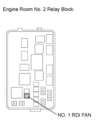
Remove the NO. 1 RDI FAN fuse from the engine room No. 2 relay block.
-
Measure the resistance according to the value(s) in the table below.
Standard Resistance Tester Connection Condition Specified Condition NO. 1 RDI FAN fuse Always Below 1 Ω -
Reinstall the NO. 1 RDI FAN fuse.
NG
REPLACE FUSE (NO. 1 RDI FAN FUSE)
OK
REPAIR OR REPLACE HARNESS OR CONNECTOR (NO. 1 COOLING FAN RELAY - BATTERY)
-
-
INSPECT COOLING FAN SYSTEM (FOR SUB FAN)
-
Disconnect the A8 ECM connector.
-
Turn the engine switch on (IG).
-
Check operation of the cooling fan (sub fan).
OK The cooling fan (sub fan) operates. -
Reconnect the A8 ECM connector.
NG
CHECK HARNESS AND CONNECTOR (COOLING FAN ECU (FOR SUB FAN) - ECM) Click here
OK
-
-
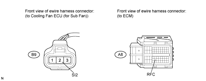
CHECK HARNESS AND CONNECTOR (COOLING FAN ECU (FOR SUB FAN) - ECM)
-
Disconnect the cooling fan ECU connector.
-
Disconnect the ECM connector.
-
Measure the resistance according to the value(s) in the table below.
Standard Resistance Tester Connection Condition Specified Condition B9-2 (SI2) - A8-43 (RFC) Always Below 1 Ω -
Reconnect the ECM connector.
-
Reconnect the cooling fan ECU connector.
NG
REPAIR OR REPLACE HARNESS OR CONNECTOR
OK
REPLACE COOLING FAN ECU (FOR SUB FAN)
-
-
CHECK HARNESS AND CONNECTOR (COOLING FAN ECU (FOR SUB FAN) - ECM)
-
Disconnect the cooling fan ECU connector.
-
Disconnect the ECM connector.
-
Measure the resistance according to the value(s) in the table below.
Standard Resistance Tester Connection Condition Specified Condition B9-2 (SI2) or A8-43 (RFC) - Body ground Always 10 kΩ or higher -
Reconnect the ECM connector.
-
Reconnect the cooling fan ECU connector.
NG
REPAIR OR REPLACE HARNESS OR CONNECTOR
OK
-
-
INSPECT NO. 2 COOLING FAN MOTOR (FOR SUB FAN)
-
Inspect the No. 2 cooling fan motor Click here.
NG
REPLACE NO. 2 COOLING FAN MOTOR (FOR SUB FAN) Click here
OK
-
-
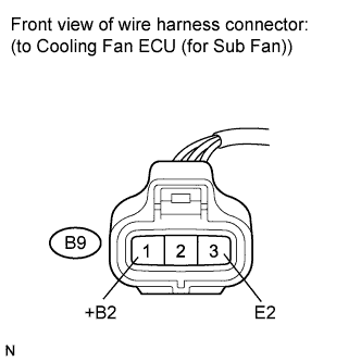
CHECK COOLING FAN ECU POWER SOURCE CIRCUIT (FOR SUB FAN)
-
Disconnect the cooling fan ECU connector.
-
Turn the engine switch on (IG).
-
Measure the voltage according to the value(s) in the table below.
Standard Voltage Tester Connection Switch Condition Specified Condition B9-1 (+B2) - B9-3 (E2) Engine switch on (IG) 11 to 14 V -
Reconnect the cooling fan ECU connector.
NG
CHECK HARNESS AND CONNECTOR (COOLING FAN ECU (FOR SUB FAN) - BODY GROUND) Click here
OK
REPLACE COOLING FAN ECU (FOR SUB FAN)
-
-
CHECK HARNESS AND CONNECTOR (COOLING FAN ECU (FOR SUB FAN) - BODY GROUND)
-
Disconnect the cooling fan ECU connector.
-
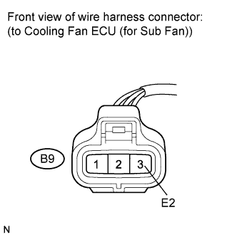
Measure the resistance according to the value(s) in the table below.
Standard Resistance Tester Connection Condition Specified Condition B9-3 (E2) - Body ground Always Below 1 Ω -
Reconnect the cooling fan ECU connector.
NG
REPAIR OR REPLACE HARNESS OR CONNECTOR
OK
-
-
INSPECT NO. 2 COOLING FAN RELAY
-
Remove the NO. 2 cooling fan relay from the engine room No. 2 relay block.
-
Measure the resistance according to the value(s) in the table below.
Standard Resistance Tester Connection Condition Specified Condition 3 - 5 No battery voltage applied to terminals 1 and 2 10 kΩ or higher 3 - 5 Battery voltage applied to terminals 1 and 2 Below 1 Ω -
Reinstall the NO. 2 cooling fan relay.
NG
REPLACE NO. 2 COOLING FAN RELAY
OK
-
-
CHECK RELAY POWER SOURCE CIRCUIT (NO. 2 COOLING FAN RELAY)
-
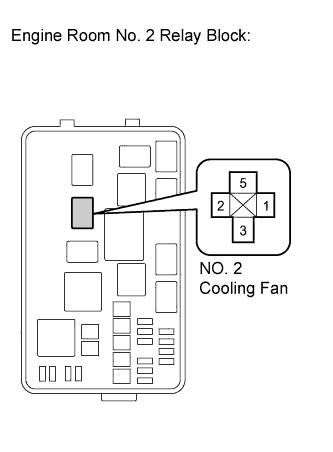
Remove the NO. 2 cooling fan relay from the engine room No. 2 relay block.
-
Measure the voltage according to the value(s) in the table below.
Standard Voltage Tester Connection Condition Specified Condition 3 (NO. 2 cooling fan relay) - Body ground Always 11 to 14 V -
Reinstall the NO. 2 cooling fan relay.
NG
INSPECT FUSE (NO. 2 RDI FAN FUSE) Click here
OK
-
-
INSPECT RELAY VOLTAGE (NO. 2 COOLING FAN RELAY)
-
Remove the NO. 2 cooling fan relay from the engine room No. 2 relay block.
-
Turn the engine switch on (IG).
-
Measure the voltage according to the value(s) in the table below.
Standard Voltage Tester Connection Switch Condition Specified Condition 1 (NO 2 cooling fan relay) - Body ground Engine switch on (IG) 11 to 14 V -
Reinstall the NO. 2 cooling fan relay.
NG
REPAIR OR REPLACE HARNESS OR CONNECTOR (NO. 2 COOLING FAN RELAY - EFI MAIN RELAY)
OK
-
-
CHECK HARNESS AND CONNECTOR (NO. 2 COOLING FAN RELAY - BODY GROUND)
-
Remove the NO. 2 cooling fan relay from the engine room No. 2 relay block.
-
Measure the resistance according to the value(s) in the table below.
Standard Resistance Tester Connection Condition Specified Condition 2 (NO. 2 cooling fan relay) - Body ground Always Below 1 Ω -
Reinstall the NO. 2 cooling fan relay.
NG
REPAIR OR REPLACE HARNESS OR CONNECTOR
OK
REPAIR OR REPLACE HARNESS OR CONNECTOR (COOLING FAN ECU (FOR SUB FAN) - NO. 2 COOLING FAN RELAY)
-
-
INSPECT FUSE (NO. 2 RDI FAN FUSE)
-
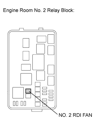
Remove the NO. 2 RDI FAN fuse from the engine room No. 2 relay block.
-
Measure the resistance according to the value(s) in the table below.
Standard Resistance Tester Connection Condition Specified Condition NO. 2 RDI FAN fuse Always Below 1 Ω -
Reinstall the NO. 2 RDI FAN fuse.
NG
REPLACE FUSE (NO. 2 RDI FAN FUSE)
OK
REPAIR OR REPLACE HARNESS OR CONNECTOR (NO. 2 COOLING FAN RELAY - BATTERY)
-
-
INSPECT COOLING FAN SYSTEM (FOR MAIN AND SUB FANS)
-
Disconnect the A8 ECM connector.
-
Turn the engine switch on (IG).
-
Check operation of the cooling fan (main and sub fans).
OK The cooling fan (main and sub fans) operates. -
Reconnect the A8 ECM connector.
NG
CHECK HARNESS AND CONNECTOR (COOLING FAN ECU (FOR MAIN FAN AND SUB FANS) - ECM) Click here
OK
-
-
CHECK HARNESS AND CONNECTOR (COOLING FAN ECU (FOR MAIN AND SUB FANS) - ECM)
-
Disconnect the cooling fan ECU connectors.
-
Disconnect the ECM connector.
-
Measure the resistance according to the value(s) in the table below.
Standard Resistance Tester Connection Condition Specified Condition B8-2 (SI) - A8-43 (RFC) Always Below 1 Ω B9-2 (SI2) - A8-43 (RFC) Always Below 1 Ω -
Reconnect the ECM connector.
-
Reconnect the cooling fan ECU connectors.
NG
REPAIR OR REPLACE HARNESS OR CONNECTOR
OK
REPLACE ECM Click here
-
-
CHECK HARNESS AND CONNECTOR (COOLING FAN ECU (FOR MAIN FAN AND SUB FANS) - ECM)
-
Disconnect the cooling fan ECU connectors.
-
Disconnect the ECM connector.
-
Measure the resistance according to the value(s) in the table below.
Standard Resistance Tester Connection Condition Specified Condition B8-2 (SI) or A8-43 (RFC) - Body ground Always 10 kΩ or higher B9-2 (SI2) or A8-43 (RFC) - Body ground Always 10 kΩ or higher -
Reconnect the ECM connector.
-
Reconnect the cooling fan ECU connectors.
NG
REPAIR OR REPLACE HARNESS OR CONNECTOR
OK
REPAIR OR REPLACE HARNESS OR CONNECTOR (NO. 1 AND NO. 2 COOLING FAN RELAY - EFI MAIN RELAY)
-