EXHAUST MANIFOLD INSTALLATION

-
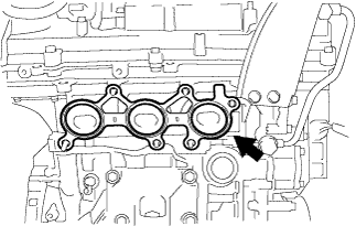
INSTALL EXHAUST MANIFOLD TO HEAD GASKET LH
-
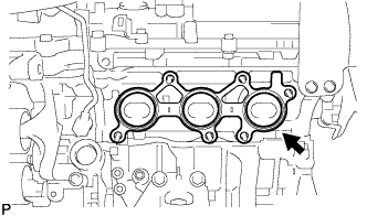
Install a new exhaust manifold to head gasket LH.
-
-
INSTALL EXHAUST MANIFOLD SUB-ASSEMBLY LH
-
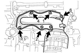
Using a 12 mm deep socket wrench, install the exhaust manifold sub-assembly LH and 6 nuts in the order shown in the illustration.
- Torque:
- 21 N*m { 214 kgf*cm, 15 ft.*lbf }
-
-
INSTALL NO. 2 EXHAUST MANIFOLD HEAT INSULATOR
-
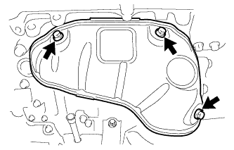
Install the No. 2 exhaust manifold heat insulator with the 3 bolts.
- Torque:
- 8.5 N*m { 87 kgf*cm, 75 in.*lbf }
-
-
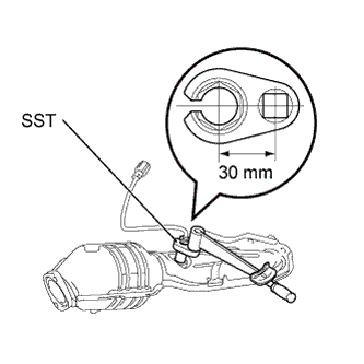
INSTALL AIR FUEL RATIO SENSOR NO.2 (for Bank 2 Sensor 1)
-
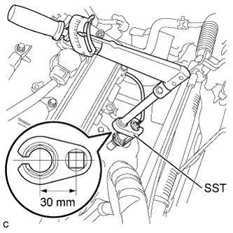
Using SST, install the air fuel ratio sensor to the exhaust manifold LH.
- SST
- 09224-00010
- Torque:
- without SST
- 44 N*m { 449 kgf*cm, 32 ft.*lbf }
- with SST
- 40 N*m { 408 kgf*cm, 30 ft.*lbf }
Note
-
The "with SST" torque value is effective when using SST with a fulcrum length of 30 mm (1.18 in.).
-
The "with SST" torque value is effective when using a torque wrench with a fulcrum length of 300 mm (11.81 in.) Click here.
-
The "with SST" torque value is effective when SST is parallel to the torque wrench.
-
Connect the air fuel ratio sensor connector.
-
-
INSTALL NO. 2 MANIFOLD STAY
-
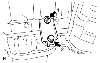
Install the No. 2 manifold stay by tightening the bolt and nut in the order shown in the illustration.
- Torque:
- 34 N*m { 347 kgf*cm, 25 ft.*lbf }
-
-
INSTALL FRONT EXHAUST PIPE ASSEMBLY
-
Install a new gasket to the front exhaust pipe assembly.
-
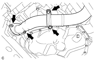
Install the front exhaust pipe assembly with the 2 nuts.
- Torque:
- 62 N*m { 632 kgf*cm, 46 ft.*lbf }
-
Install the No. 1 exhaust pipe support bracket with the 2 bolts.
- Torque:
- 21 N*m { 214 kgf*cm, 15 ft.*lbf }
-
Connect the No. 2 oxygen sensor connector (for Bank 2).
-
-
INSTALL AIR FUEL RATIO SENSOR (for Bank 1 Sensor 1)
-
Using SST, install the air fuel ratio sensor to the exhaust manifold RH.
- SST
- 09224-00010
- Torque:
- without SST
- 44 N*m { 449 kgf*cm, 32 ft.*lbf }
- with SST
- 40 N*m { 408 kgf*cm, 30 ft.*lbf }
Note
-
The "with SST" torque value is effective when using SST with a fulcrum length of 30 mm (1.18 in.).
-
The "with SST" torque value is effective when using a torque wrench with a fulcrum length of 300 mm (11.81 in.) Click here.
-
The "with SST" torque value is effective when SST is parallel to the torque wrench.
-
Connect the air fuel ratio sensor connector.
-
-
INSTALL EXHAUST MANIFOLD TO HEAD GASKET
-
Install a new exhaust manifold to head gasket.
-
-
INSTALL EXHAUST MANIFOLD SUB-ASSEMBLY RH
-

Using a 12 mm deep socket wrench, install the exhaust manifold sub-assembly RH by tightening the 6 nuts in the order shown in the illustration.
- Torque:
- 21 N*m { 214 kgf*cm, 15 ft.*lbf }
-
Connect the air fuel ratio sensor connector (for Bank 1 Sensor 1).
-
-
INSTALL MANIFOLD STAY
-
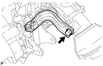
Install the manifold stay with the bolt.
- Torque:
- 34 N*m { 347 kgf*cm, 25 ft.*lbf }
-
-
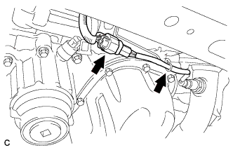
INSTALL CENTER EXHAUST PIPE ASSEMBLY (for Front Side)
-
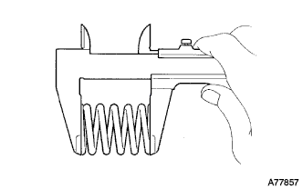
Using a vernier caliper, measure the free length of the compression springs.
Minimum length 43.0 mm (1.693 in.) If the free length is less than the minimum, replace the compression spring.
-
Fully insert a new gasket to the center exhaust pipe assembly (for Front Side).
-
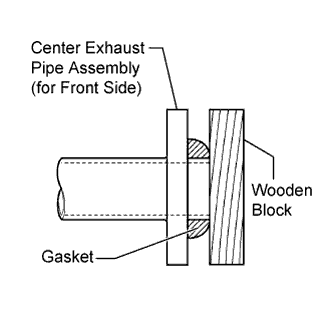
Using a plastic hammer and wooden block, tap in the new gasket until its surface is flush with the center exhaust pipe assembly (for Front Side).
Note
-
Be sure to install the gasket in the correct direction.
-
Do not reuse the gasket.
-
Do not damage the gasket.
-
Do not push in the gasket by using the exhaust pipe when connecting it.
-
-
Install 2 new gaskets to the center exhaust pipe assembly (for Front Side).
-
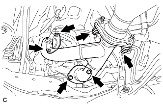
Install the center exhaust pipe assembly (for Front Side) with the 4 bolts, 2 compression springs and 2 nuts.
- Torque:
- Bolt
- 43 N*m { 440 kgf*cm, 32 ft.*lbf }
- Nut
- 62 N*m { 632 kgf*cm, 46 ft.*lbf }
-
-
INSTALL AIR CLEANER CAP SUB-ASSEMBLY
-
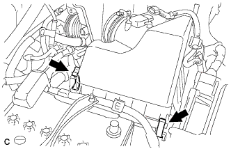
Install the air cleaner cap sub-assembly to the air cleaner case with the 2 clamps.
-
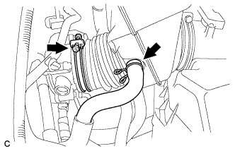
Connect the air cleaner hose to the throttle body with the hose clamp.
-
Connect the ventilation hose.
-
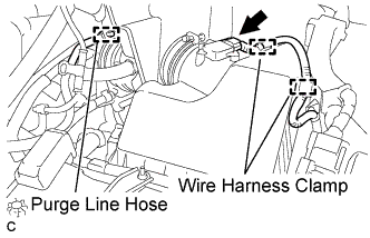
Connect the purge line hose.
-
Connect the 2 wire harness clamps and mass air flow meter connector.
-
-
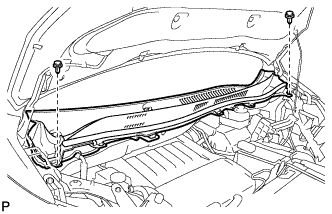
INSTALL COWL TOP PANEL OUTER SUB-ASSEMBLY
-
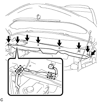
Install the outer cowl top panel with the 8 bolts.
- Torque:
- 8.8 N*m { 90 kgf*cm, 78 in.*lbf }
-
Connect the 2 clamps to the outer cowl top panel.
-
Remove the protective tape.
-
-
INSTALL RESERVOIR BRACKET
-
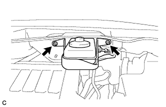
Install the brake master cylinder reservoir with bracket to the outer cowl top panel with the 2 nuts.
- Torque:
- 6.5 N*m { 66 kgf*cm, 58 in.*lbf }
-
-
INSTALL WINDSHIELD WIPER MOTOR AND LINK ASSEMBLY
-
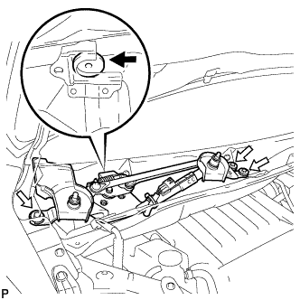
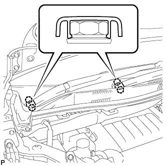
Install the windshield wiper motor and link assembly with the 3 bolts as shown in the illustration.
- Torque:
- 5.5 N*m { 56 kgf*cm, 49 in.*lbf }
-
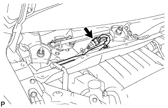
Connect the connector.
-
-
INSTALL COWL TOP VENTILATOR LOUVER SUB-ASSEMBLY
-
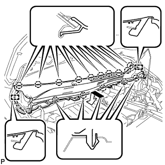
Engage the 15 claws and 2 guides to install the cowl top ventilator louver sub-assembly as shown in the illustration.
-
Install the 2 clips.
-
-
INSTALL WINDSHIELD WIPER ARM AND BLADE ASSEMBLY RH
-
Operate the wiper and stop the windshield wiper motor at the automatic stop position.
-
When reusing the front wiper arm and blade assembly RH:
-
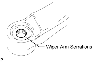
Clean the wiper arm serrations.
-
-
When reusing the windshield wiper link assembly:
-
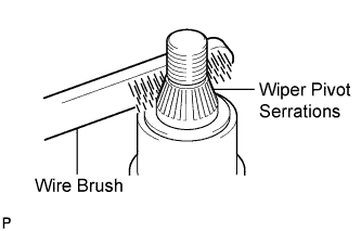
Clean the wiper pivot serrations with a wire brush.
-
-
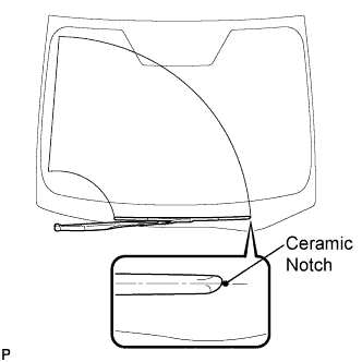
Install the front wiper arm and blade assembly RH with the nut to the position shown in the illustration.
- Torque:
- 24 N*m { 245 kgf*cm, 18 ft.*lbf }
-
-
INSTALL WINDSHIELD WIPER ARM AND BLADE ASSEMBLY LH
-
When reusing the front wiper arm and blade assembly LH:
-
Clean the wiper arm serrations.
-
-
When reusing the windshield wiper link assembly:
-
Clean the wiper pivot serrations with a wire brush.
-
-
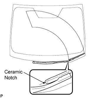
Install the front wiper arm and blade assembly LH with the nut to the position shown in the illustration.
- Torque:
- 24 N*m { 245 kgf*cm, 18 ft.*lbf }
-
Operate the front wipers while spraying washer fluid onto the windshield. Make sure that the front wipers function properly and the wipers do not come into contact with the vehicle body.
-
-
INSTALL WINDSHIELD WIPER ARM COVER
-
Engage the 2 claws to install the 2 windshield wiper arm covers.
-
-
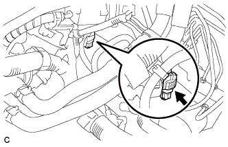
CONNECT OXYGEN SENSOR (for Bank 1 Sensor 2)
-
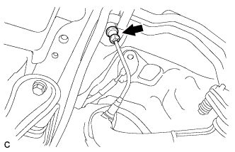
Install the grommet to the vehicle.
-
Connect the oxygen sensor connector (for Bank 1 Sensor 2).
-
-
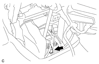
INSTALL INSTRUMENT CLUSTER FINISH PANEL ASSEMBLY
-
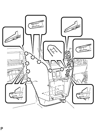
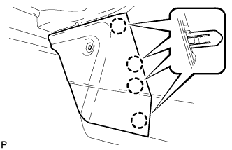
Engage the 15 claws.
Tech Tips
Before engaging the 15 claws, make sure that the claws are positioned correctly.
Note
Make sure that the claws are fully engaged.
-
Install the instrument cluster finish panel assembly with the bolt <C>.
-
-
INSTALL INSTRUMENT PANEL BOX ASSEMBLY
-
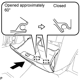
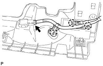
With the instrument panel box assembly opened approximately 60° from its closed position, engage the 2 hinges horizontally.
Note
Engaging the hinges from the top will deform the hinges. Be sure to install the instrument panel box assembly horizontally.
-
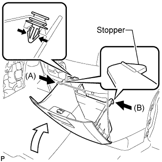
Install the damper clip.
-
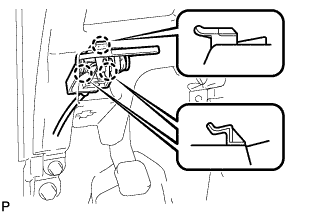
Slightly bend stoppers (A) and (B) in the directions indicated by the arrows in the illustration and engage the stoppers to install the instrument panel box assembly.
-
-
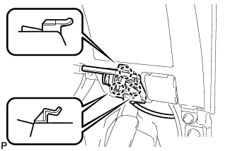
INSTALL GLOVE COMPARTMENT DOOR ASSEMBLY
-
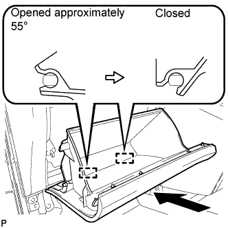
With the glove compartment door assembly opened approximately 55° from its closed position, engage the 2 hinges horizontally.
Note
Engaging the hinges from the top will deform the hinges. Be sure to install the glove compartment door assembly horizontally.
-
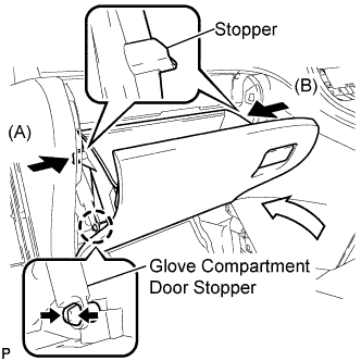
Slightly bend stoppers (A) and (B) in the directions indicated by the arrows in the illustration and engage the stoppers to install the glove compartment door assembly.
-
Engage the claw and connect the glove compartment door stopper.
-
-
INSTALL CENTER FLOOR CARPET COVER LH
-
Engage the 4 claws.
-

Install the center floor carpet cover LH with the clip.
-
-
INSTALL CENTER FLOOR CARPET COVER RH (for RHD)
-
Engage the 4 claws.
-
Install the center floor carpet cover RH with the 2 clips.
-
-
INSTALL CENTER FLOOR CARPET COVER RH (for LHD)
-
Engage the 5 claws.
-
Install the center floor carpet cover RH with the clip.
-
-
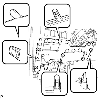
INSTALL LOWER INSTRUMENT PANEL FINISH PANEL (for RHD)
-
Engage the 3 guides and 14 claws.
Tech Tips
Make sure that all claws around the entire circumference of the driver side knee airbag assembly are fully engaged.
Note
Make sure that the claws are fully engaged.
-
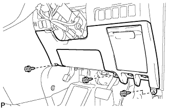
Install the lower instrument panel finish panel with the 3 screws <B>.
-

Engage the 3 claws and the fuel lid lock control cable assembly.
-
Engage the 3 claws and the hood lock control cable assembly.
-
-
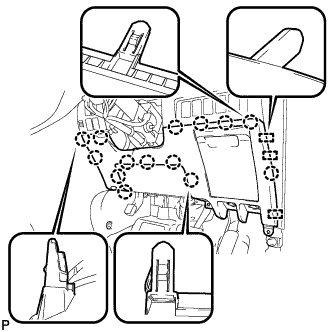
INSTALL LOWER INSTRUMENT PANEL FINISH PANEL (for LHD)
-
Engage the 3 guides, 13 claws and clip.
Tech Tips
Make sure that all claws around the entire circumference of the driver side knee airbag assembly are fully engaged.
Note
Make sure that the claws are fully engaged.
-
Install the lower instrument panel finish panel with the 3 screws <B>.
-

Connect the fuel filler opening lid lock sub-assembly to the fuel lid lock open lever sub-assembly.
-
Engage the 3 claws and the fuel lid lock control cable assembly.
-

Engage the 3 claws and the hood lock control cable assembly.
-
-
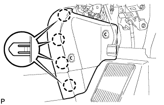
INSTALL NO. 1 INSTRUMENT PANEL UNDER COVER SUB-ASSEMBLY (for RHD)
-
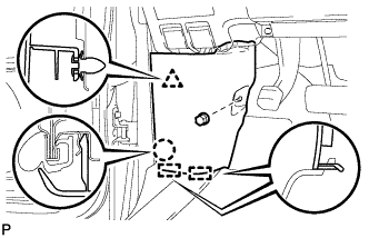
Engage the 2 claws and DLC3.
-
Engage the clamp.
-
Connect the connector.
-

Engage the 2 claws and 2 guides.
Note
Make sure that the claws are fully engaged.
-
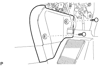
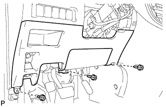
Install the No. 1 instrument panel under cover sub-assembly with the 2 screws <B>.
-
-
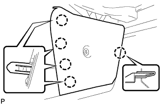
INSTALL NO. 1 INSTRUMENT PANEL UNDER COVER SUB-ASSEMBLY (for LHD)
-
Engage the clamp.
-
Connect each connector.
-

Engage the 2 claws and guide.
Note
Make sure that the claws are fully engaged.
-
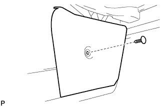
Install the No. 1 instrument panel under cover sub-assembly with the 2 screws <B>.
-
-
INSTALL COWL SIDE TRIM BOARD RH (for RHD)
-

Engage the 2 guides, claw and clip to install the cowl side trim board RH.
-
Install the clip(A).
-
-
INSTALL COWL SIDE TRIM BOARD LH (for LHD)
-
Engage the 2 guides, claw and clip to install the cowl side trim board LH.
-
Install the clip(A).
-
-
INSTALL RADIATOR ASSEMBLY
-
Install the radiator assembly Click here.
-
-
INSPECT FOR EXHAUST GAS LEAKS