- Click here
REMOVE RADIATOR ASSEMBLY
-
Remove the radiator assembly (Click here).
-
- Click here
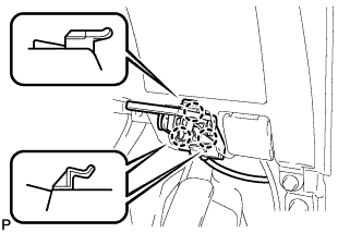
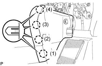
REMOVE COWL SIDE TRIM BOARD RH (for RHD)
-

Remove the clip.
-
Disengage the clip, claw and 2 guides, and remove the cowl side trim board RH.
-
- Click here
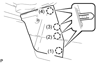
REMOVE COWL SIDE TRIM BOARD LH (for LHD)
-
Remove the clip.
-
Disengage the 2 clips, claw and 2 guides, and remove the cowl side trim board RH.
-
- Click here
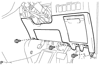
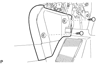
REMOVE NO. 1 INSTRUMENT PANEL UNDER COVER SUB-ASSEMBLY (for RHD)
-

Remove the 2 screws <B>.
-
Disengage the 2 claws and 2 guides.
-
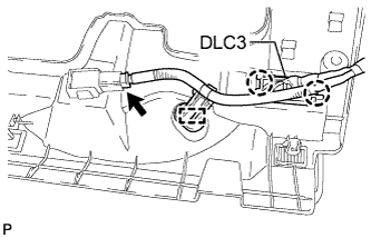
Disengage the 2 claws and disconnect the DLC3.
-
Disengage the clamp.
-
Disconnect each connector and remove the No. 1 instrument panel under cover sub-assembly.
-
- Click here
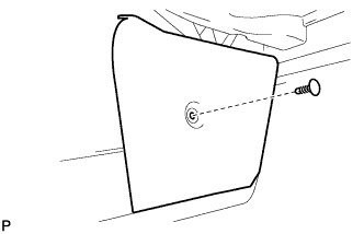
REMOVE NO. 1 INSTRUMENT PANEL UNDER COVER SUB-ASSEMBLY (for LHD)
-

Remove the 2 screws <B>.
-
Disengage the 2 claws and guide.
-
Disengage the clamp.
-
Disconnect each connector and remove the No. 1 instrument panel under cover sub-assembly.
-
- Click here
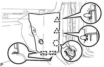
REMOVE LOWER INSTRUMENT PANEL FINISH PANEL (for RHD)
-
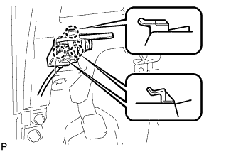
Disengage the 3 claws and disconnect the hood lock control cable assembly.
-

Disengage the 3 claws and disconnect the fuel lid lock control cable assembly.
-
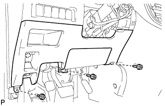
Remove the 3 screws <B>.
-
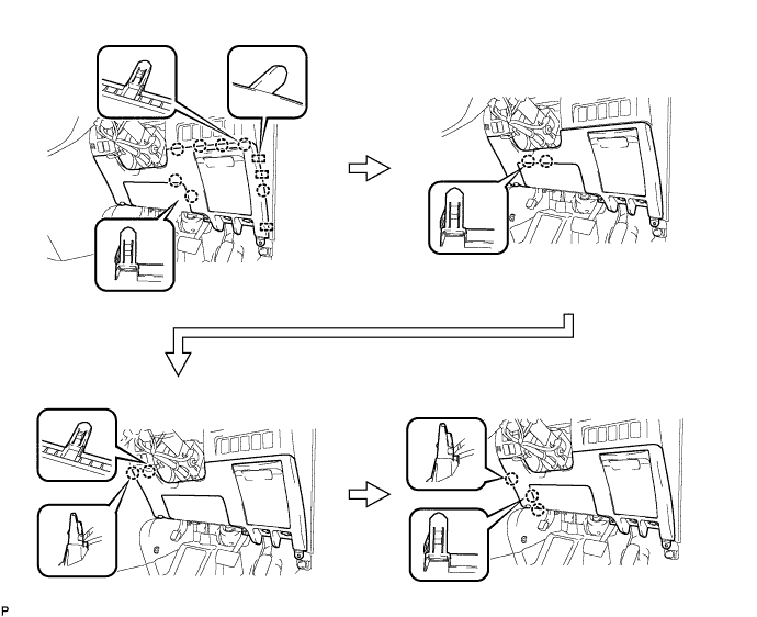
Disengage the 14 claws and the 3 guides, and remove the lower instrument panel finish panel as shown in the illustration.
Note:
-
Make sure to follow the order shown in the illustration to avoid damage to the lower instrument panel finish panel.
-
While supporting the knee airbag, remove the lower instrument panel finish panel.
-
-
- Click here
REMOVE LOWER INSTRUMENT PANEL FINISH PANEL (for LHD)
-

Disengage the 3 claws and disconnect the hood lock control cable assembly.
-
Disengage the 3 claws and disconnect the fuel lid lock control cable assembly.
-

Disconnect the fuel filler opening lid lock sub-assembly and remove the fuel lid lock open lever sub-assembly.
-
Remove the 3 screws <B>.
-
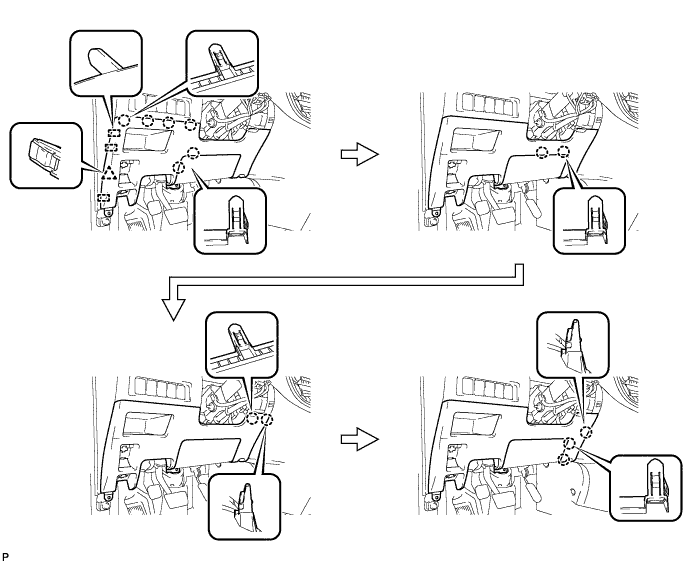
Disengage the 13 claws, clip and the 3 guides and remove the lower instrument panel finish panel as shown in the illustration.
Note:
-
Make sure to follow the order shown in the illustration to avoid damage to the lower instrument panel finish panel.
-
While supporting the knee airbag, remove the lower instrument panel finish panel.
-
-
- Click here
REMOVE CENTER FLOOR CARPET COVER LH
-

Using a clip remover, remove the clip.
-
Disengage the 4 claws and remove the center floor carpet cover LH in the order shown in the illustration.
Tip:Remove the center floor carpet cover LH while pushing on the instrument cluster finish panel.
-
- Click here
REMOVE CENTER FLOOR CARPET COVER RH (for RHD)
-
Using a clip remover, remove the 2 clips.
-
Disengage the 4 claws and remove the center floor carpet cover RH in the order shown in the illustration.
Tip:Remove the center floor carpet cover RH while pushing on the instrument cluster finish panel.
-
- Click here
REMOVE CENTER FLOOR CARPET COVER RH (for LHD)
-
Using a clip remover, remove the clip.
-
Disengage the 5 claws and remove the center floor carpet cover RH in the order shown in the illustration.
Tip:Remove the center floor carpet cover RH while pushing on the instrument cluster finish panel.
-
- Click here
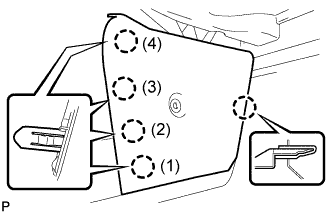
REMOVE GLOVE COMPARTMENT DOOR ASSEMBLY
-
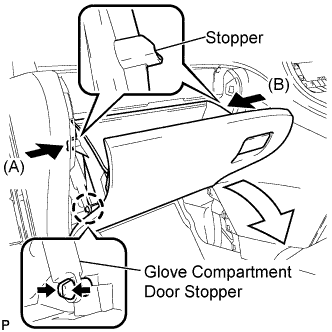
Disengage the claw and release the glove compartment door stopper.
-
Slightly bend stoppers (A) and (B) in the directions indicated by the arrows in the illustration and pull the glove compartment door assembly until the stoppers are released.
-
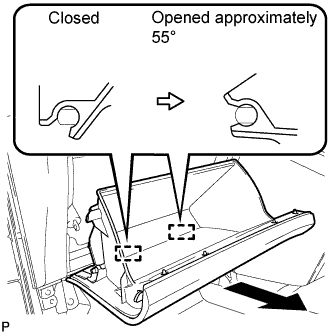
Open the glove compartment door assembly to approximately 55° from its closed position. Pull it horizontally toward the rear of the vehicle to disengage the 2 hinges and remove the glove compartment door assembly.
Note:Pulling the glove compartment door assembly upward to remove it causes the hinges to deform. Be sure to pull out the glove compartment door assembly horizontally.
-
- Click here
REMOVE INSTRUMENT PANEL BOX ASSEMBLY
-
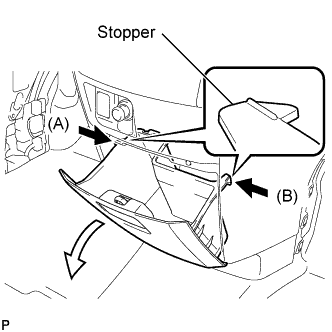
Slightly bend stoppers (A) and (B) in the directions indicated by the arrows in the illustration and pull the instrument panel box assembly until the stoppers are released.
-
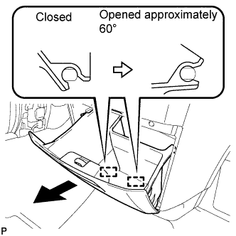
Open the instrument panel box assembly to approximately 60° from its closed position. Pull it horizontally toward the rear of the vehicle to disengage the 2 hinges and remove the instrument panel box assembly.
Note:Pulling the instrument panel box assembly upward to remove it causes the hinges to deform. Be sure to pull out the instrument panel box horizontally.
-
- Click here
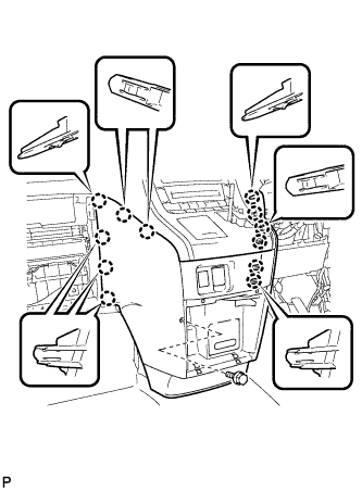
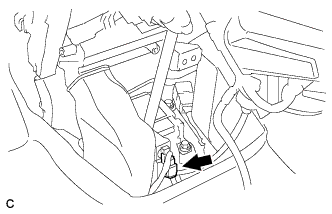
REMOVE INSTRUMENT CLUSTER FINISH PANEL ASSEMBLY
-
Remove the bolt <C>.
-
Disengage the 12 claws.
Tip:First disengage the 6 claws for the right side and then pull the panel to the rear of the vehicle to disengage the 6 claws for the left side.
-
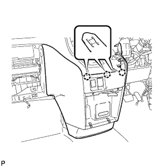
Disengage the 3 claws.
-
Disconnect each connector and remove the instrument cluster finish panel assembly.
-
- Click here
DISCONNECT OXYGEN SENSOR (for Bank 1 Sensor 2)
-
Disconnect the oxygen sensor connector (for Bank 1 Sensor 2).
-
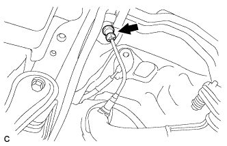
Remove the grommet.
-
- Click here
REMOVE WINDSHIELD WIPER ARM COVER
-
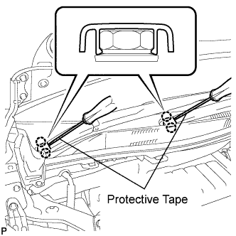
Using a screwdriver, disengage the 2 claws and remove the 2 windshield wiper arm covers.
Tip:Tape the screwdriver tip before use.
-
- Click here
REMOVE WINDSHIELD WIPER ARM AND BLADE ASSEMBLY RH
-
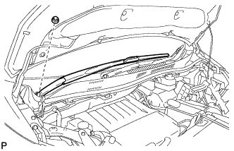
Remove the nut and the front wiper arm and blade assembly RH.
-
- Click here
REMOVE WINDSHIELD WIPER ARM AND BLADE ASSEMBLY LH
-
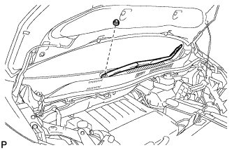
Remove the nut and the front wiper arm and blade assembly LH.
-
- Click here
REMOVE COWL TOP VENTILATOR LOUVER SUB-ASSEMBLY
-
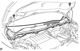
Remove the 2 clips.
-
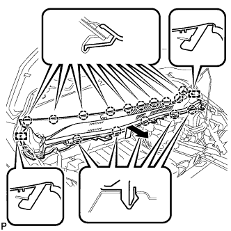
Disengage the 15 claws and 2 guides, and remove the cowl top ventilator louver sub-assembly as shown in the illustration.
-
- Click here
REMOVE WINDSHIELD WIPER MOTOR AND LINK ASSEMBLY
-
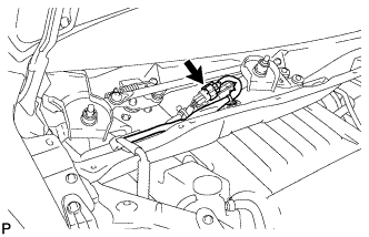
Disconnect the connector.
-
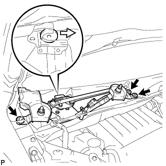
Remove the 3 bolts and the windshield wiper motor and link assembly as shown in the illustration.
-
- Click here
SEPARATE RESERVOIR BRACKET
-
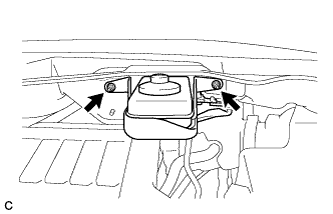
Remove the 2 nuts and separate the brake master cylinder reservoir with bracket from the outer cowl top panel.
-
- Click here
REMOVE COWL TOP PANEL OUTER SUB-ASSEMBLY
- Click here
REMOVE AIR CLEANER CAP SUB-ASSEMBLY
-
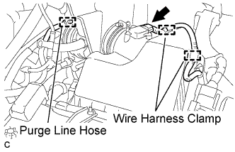
Separate the mass air flow meter connector and 2 wire harness clamps.
-
Separate the purge line hose.
-
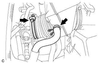
Separate the ventilation hose.
-
Loosen the hose clamp and separate the air cleaner hose from the throttle body.
-
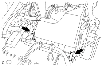
Release the 2 clamps and remove the air cleaner cap sub-assembly.
-
- Click here
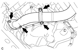
REMOVE CENTER EXHAUST PIPE ASSEMBLY (for Front Side)
-
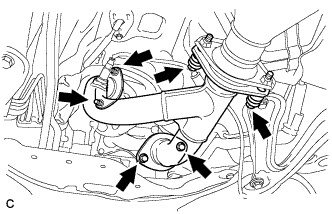
Remove the 4 bolts, 2 nuts, 2 compression springs and center exhaust pipe assembly (for Front Side).
-
Remove the 3 gaskets from the center exhaust pipe assembly (for Front Side).
-
- Click here
SEPARATE MANIFOLD STAY
-
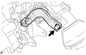
Remove the bolt and separate the manifold stay.
-
- Click here
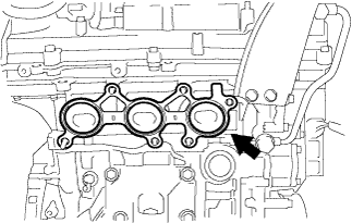
REMOVE EXHAUST MANIFOLD SUB-ASSEMBLY RH
-
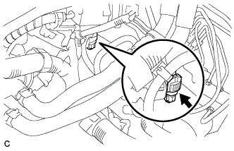
Disconnect the air fuel ratio sensor connector (for Bank 1 Sensor 1).
-
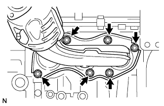
Using a 12 mm deep socket wrench, remove the 6 nuts and exhaust manifold sub-assembly RH.
-
- Click here
REMOVE EXHAUST MANIFOLD TO HEAD GASKET
-
Remove the exhaust manifold to head gasket from the cylinder head sub-assembly.
-
- Click here
REMOVE AIR FUEL RATIO SENSOR (for Bank 1 Sensor 1)
-
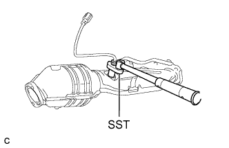
Using SST, remove the air fuel ratio sensor from the exhaust manifold RH.
09224-00010
-
- Click here
REMOVE FRONT EXHAUST PIPE ASSEMBLY
-
Disconnect the No. 2 oxygen sensor connector (for Bank 2).
-
Remove the 2 bolts and No. 1 exhaust pipe support bracket.
-
Remove the 2 nuts and front exhaust pipe assembly.
-
Remove the gasket from the front exhaust pipe assembly.
-
- Click here
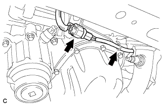
REMOVE NO. 2 MANIFOLD STAY
-
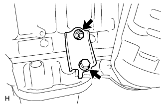
Remove the bolt, nut and No. 2 manifold stay.
-
- Click here
REMOVE AIR FUEL RATIO SENSOR NO.2 (for Bank 2 Sensor 1)
-
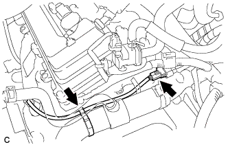
Disconnect the air fuel ratio sensor connector, and separate the wire harness clamp.
-
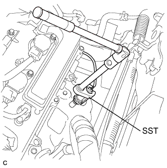
Using SST, remove the air fuel ratio sensor from the exhaust manifold LH.
09224-00010
-
- Click here
REMOVE NO. 2 EXHAUST MANIFOLD HEAT INSULATOR
-
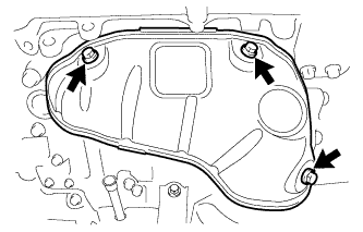
Remove the 3 bolts and No. 2 exhaust manifold heat insulator.
-
- Click here
REMOVE EXHAUST MANIFOLD SUB-ASSEMBLY LH
-
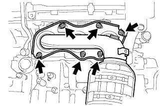
Using a 12 mm deep socket wrench, remove the 6 nuts and exhaust manifold sub-assembly LH.
-
- Click here
REMOVE EXHAUST MANIFOLD TO HEAD GASKET LH
-
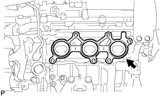
Remove the exhaust manifold to head gasket LH from the cylinder head sub-assembly.
-