EXHAUST MANIFOLD INSTALLATION

-
INSTALL NO. 1 MANIFOLD CONVERTER INSULATOR
-
Install the No. 1 manifold converter insulator with the 4 bolts.
- Torque:
- 12 N*m { 122 kgf*cm, 9 ft.*lbf }
-
-
INSTALL NO. 2 EXHAUST MANIFOLD HEAT INSULATOR
-
Install the No. 2 exhaust manifold heat insulator with the 2 bolts.
- Torque:
- 12 N*m { 122 kgf*cm, 9 ft.*lbf }
-
-
INSTALL EXHAUST MANIFOLD CONVERTER SUB-ASSEMBLY
-
Install a new exhaust manifold to head gasket.
-
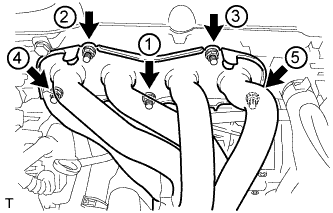
Using a 12 mm deep socket wrench, install the exhaust manifold converter sub-assembly and 5 nuts in the order shown in the illustration.
- Torque:
- 37 N*m { 377 kgf*cm, 27 ft.*lbf }
-
-
INSTALL NO. 2 MANIFOLD STAY
-
Install the No. 2 manifold stay with the bolt and nut.
- Torque:
- 44 N*m { 449 kgf*cm, 33 ft.*lbf }
-
-
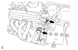
INSTALL MANIFOLD STAY
-
Install the manifold stay with the bolt and nut.
- Torque:
- 44 N*m { 449 kgf*cm, 33 ft.*lbf }
-
-
INSTALL FRONT ENGINE MOUNTING BRACKET
-
Install the front engine mounting bracket to the continuously variable transaxle assembly with the 3 bolts.
- Torque:
- 64 N*m { 653 kgf*cm, 47 ft.*lbf }
-
-
INSTALL FRONT ENGINE MOUNTING INSULATOR
-
Install the front engine mounting insulator with the 2 bolts.
- Torque:
- 95 N*m { 969 kgf*cm, 70 ft.*lbf }
-
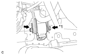
Text in Illustration *1 Bolt Install the front engine mounting insulator with the bolt and nut to the front engine mounting bracket.
- Torque:
- 145 N*m { 1479 kgf*cm, 107 ft.*lbf }
Tech Tips
Tighten from the bolt side.
-
-
INSTALL AIR FUEL RATIO SENSOR
-
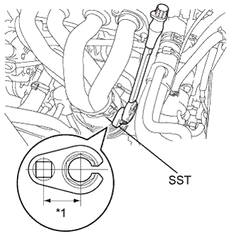
Text in Illustration *1 Fulcrum Length
30 mm
Using SST, install the air fuel ratio sensor.
- SST
- 09224-00010
- Torque:
- without SST
- 44 N*m { 449 kgf*cm, 32 ft.*lbf }
- with SST
- 39 N*m { 398 kgf*cm, 29 ft.*lbf }
Note
-
The "with SST" torque value is effective when using SST with a fulcrum length of 30 mm (1.18 in.).
-
The "with SST" torque value is effective when using a torque wrench with a fulcrum length of 260 mm (10.23 in.) Click here.
-
This torque value is effective when SST is parallel to the torque wrench.
-
Connect the air fuel ratio sensor connector and wire harness clamp.
-
-
INSTALL NO. 1 EXHAUST MANIFOLD HEAT INSULATOR
-
Install the No. 1 exhaust manifold heat insulator with the 4 bolts.
- Torque:
- 12 N*m { 122 kgf*cm, 9 ft.*lbf }
-
-
INSTALL FRONT EXHAUST PIPE ASSEMBLY
-
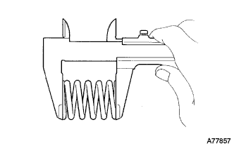
Using a vernier caliper, measure the free length of the compression springs.
Minimum length 41.5 mm (1.64 in.) If the free length is less than the minimum, replace the compression spring.
-
Fully insert a new gasket to the exhaust manifold converter sub-assembly.
-
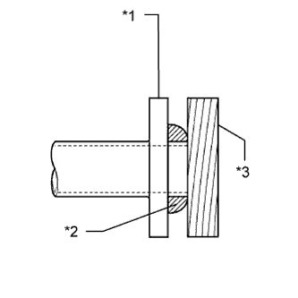
Text in Illustration *1 Exhaust Manifold Converter Sub-assembly *2 Gasket *3 Wooden Block Using a plastic hammer and wooden block, tap in the new gasket until its surface is flush with the exhaust manifold converter sub-assembly.
Note
-
Be sure to install the gasket in the correct direction.
-
Do not reuse the gasket.
-
Do not damage the gasket.
-
Do not push in the gasket by using the exhaust pipe when connecting it.
-
-
Install a new gasket to the front exhaust pipe assembly.
-
Install the front exhaust pipe assembly with the 4 bolts and 2 compression springs.
- Torque:
- 43 N*m { 440 kgf*cm, 32 ft.*lbf }
-
Connect the oxygen sensor connector.
-
-
INSTALL NO. 1 ENGINE UNDER COVER
-
INSTALL GENERATOR ASSEMBLY
-
Install the generator assembly Click here.
-
-
INSPECT FOR EXHAUST GAS LEAK