CYLINDER BLOCK REASSEMBLY

Tech Tips
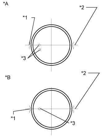
Check whether the engine is TMC made or not by referring to the following illustration.
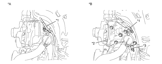
| *A | for TMC Made Engine | *B | except TMC Made Engine |
| *1 | Engine Oil Level Dipstick Guide | *2 | Water Inlet Housing |
| *3 | Water Inlet Housing Drain Cock Assembly | - | - |
-
INSTALL RING PIN
-
Using a plastic hammer, tap in the ring pins.
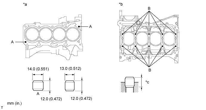
Text in Illustration *a Upper Side *b Lower Side *c Protrusion Height - - Standard Protrusion Item Protrusion A 6 mm (0.236 in.) B 5 mm (0.197 in.)
-
-
INSTALL STUD BOLT (for TMC Made Engine)
-
Using an E5 or E7 "TORX" socket, install the stud bolts.
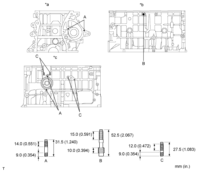
Text in Illustration *a Front Side *b RH Side *c LH Side - - - Torque:
- Stud Bolt A, C
- 5.0 N*m { 51 kgf*cm, 44 in.*lbf }
- Stud Bolt B
- 9.5 N*m { 97 kgf*cm, 84 in.*lbf }
-
-
INSTALL STUD BOLT (except TMC Made Engine)
-
Using an E5 or E7 "TORX" socket, install the stud bolts.
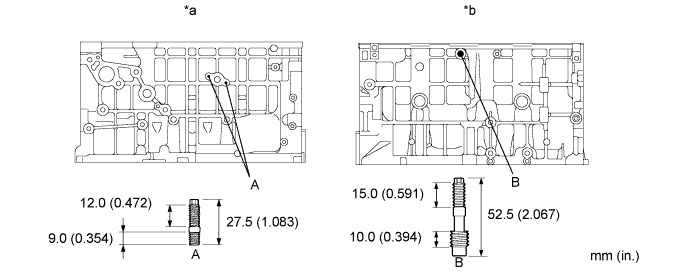
Text in Illustration *a LH Side *b RH Side - Torque:
- Stud Bolt A, C
- 5.0 N*m { 51 kgf*cm, 44 in.*lbf }
- Stud Bolt B
- 9.5 N*m { 97 kgf*cm, 84 in.*lbf }
-
-
INSTALL STRAIGHT PIN (for TMC Made Engine)
-
Using a plastic hammer, tap in the straight pins.
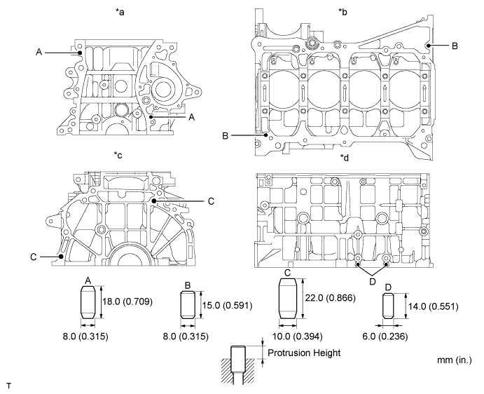
Text in Illustration *a Front Side *b Lower Side *c Rear Side *d RH Side Standard Protrusion Item Protrusion A 8 mm (0.315 in.) B 7.5 mm (0.295 in.) C 12 mm (0.472 in.) D 5 mm (0.197 in.)
-
-
INSTALL STRAIGHT PIN (except TMC Made Engine)
-
Using a plastic hammer, tap in the straight pins.
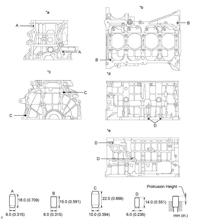
Text in Illustration *a Front Side *b Lower Side *c Rear Side *d RH Side *e LH Side - - Standard Protrusion Item Protrusion A 8 mm (0.315 in.) B 7.5 mm (0.295 in.) C 12 mm (0.472 in.) D 5 mm (0.197 in.)
-
-
INSPECT CRANKSHAFT OIL CLEARANCE
-
Check the crank journal and bearing for pitting and scratches.
-
Install the crankshaft bearing Click here.
-
Place the crankshaft on the cylinder block.
-
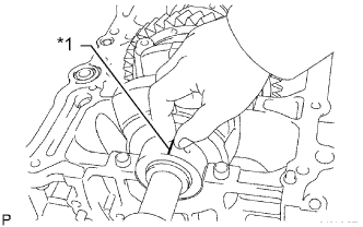
Text in Illustration *1 Plastigage Lay a strip of Plastigage across each journal.
-
Examine the front marks and numbers and install the bearing caps on the cylinder block.
Tech Tips
A number is marked on each main bearing cap to indicate the installation position.
-
Install the main bearing caps Click here.
Note
Do not turn the crankshaft.
-
Remove the main bearing caps Click here.
-
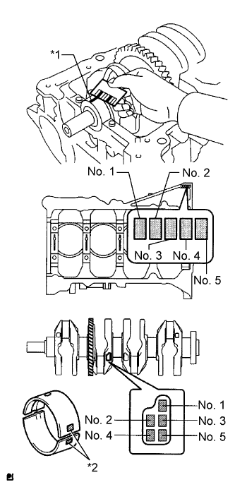
Text in Illustration *1 Plastigage *2 Number Mark Measure the Plastigage at its widest point.
Standard oil clearance 0.008 to 0.024 mm (0.000315 to 0.000945 in.) Maximum oil clearance 0.05 mm (0.00197 in.) Note
Remove the Plastigage completely after the measurement.
If the oil clearance is greater than the maximum, replace the crankshaft bearing. If necessary, replace the crankshaft.
Tech Tips
-
If replacing a bearing, select a new one with the same number. If the number of the bearing cannot be determined, calculate the correct bearing number by adding together the numbers imprinted on the cylinder block and crankshaft. Then select a new bearing with the calculated number. There are 4 sizes of standard bearings, marked "1", "2", "3" and "4" accordingly.
-
EXAMPLE: Cylinder block "3" + Crankshaft "5" = Total number 8 (Use bearing "3")
Cylinder block + Crankshaft 0 to 2 3 to 5 6 to 8 9 to 11 Bearing to be used "1" "2" "3" "4" Standard Cylinder Block Journal Bore Diameter Mark Specified Condition 0 59.000 to 59.002 mm (2.32283 to 2.32291 in.) 1 59.003 to 59.004 mm (2.32295 to 2.32299 in.) 2 59.005 to 59.006 mm (2.32303 to 2.32307 in.) 3 59.007 to 59.009 mm (2.32311 to 2.32318 in.) 4 59.010 to 59.011 mm (2.32322 to 2.32326 in.) 5 59.012 to 59.013 mm (2.32330 to 2.32334 in.) 6 59.014 to 59.016 mm (2.32338 to 2.32346 in.) Standard Crankshaft Journal Diameter Mark Specified Condition 0 54.999 to 55.000 mm (2.16531 to 2.16535 in.) 1 54.997 to 54.998 mm (2.16523 to 2.16527 in.) 2 54.995 to 54.996 mm (2.16515 to 2.16519 in.) 3 54.993 to 54.994 mm (2.16507 to 2.16511 in.) 4 54.991 to 54.992 mm (2.16500 to 2.16504 in.) 5 54.988 to 54.990 mm (2.16488 to 2.16496 in.) Standard Bearing Center Wall Thickness Mark Specified Condition 1 1.993 to 1.996 mm (0.078464 to 0.078583 in.) 2 1.997 to 1.999 mm (0.078622 to 0.078701 in.) 3 2.000 to 2.002 mm (0.078740 to 0.078819 in.) 4 2.003 to 2.005 mm (0.078858 to 0.078937 in.) -
-
-
INSTALL NO. 1 OIL NOZZLE SUB-ASSEMBLY
-

Using a 5 mm hexagon wrench, install the oil nozzles with the bolts.
- Torque:
- 7.0 N*m { 71 kgf*cm, 62 in.*lbf }
-
-
INSTALL PISTON
-
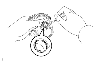
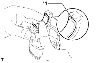
Using a screwdriver, install a new snap ring at one end of the piston pin hole.
Tech Tips
Make sure that the end gap on the snap ring is not aligned with the pin hole cutout portion of the piston.
-
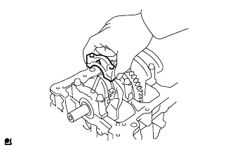
Gradually heat the piston to approximately 80 to 90 °C (176 to 194°F).
-
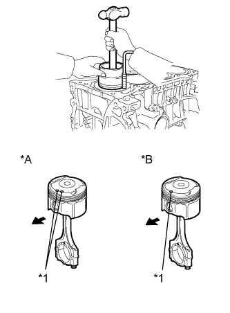
for 2-piece Type:
-
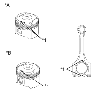
Text in Illustration *A for TMC Made Engine *B except TMC Made Engine *1 Front Mark Align the front marks on the piston and connecting rod, and push in the piston with a thumb.
-
-
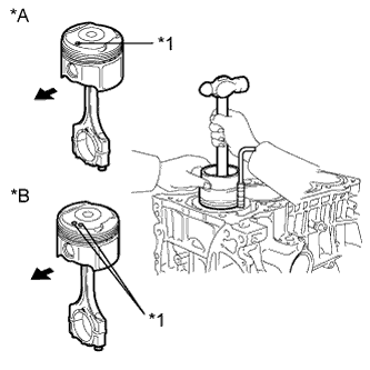
for 3-piece Type:
-
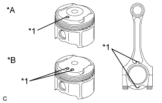
Text in Illustration *A for TMC Made Engine *B except TMC Made Engine *1 Front Mark Align the front marks on the piston and connecting rod, and push in the piston with a thumb.
-
-
Using a screwdriver, install a new snap ring on the other end of the piston pin hole.
Tech Tips
Make sure that the end gap on the snap ring is not aligned with the pin hole cutout portion of the piston.
-
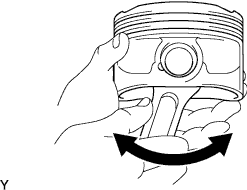
Check the fitting condition between the piston and piston pin by trying to move the piston back and forth on the piston pin.
-
-
INSTALL PISTON RING SET
-
for 2-piece Type:
-
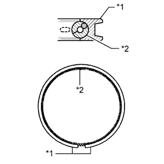
Text in Illustration *1 Oil Ring *2 Oil Ring (Expander) Install the oil ring expander and oil ring rail by hand.
Note
-
Install the expander and oil ring so that their ring ends are at opposite sides.
-
Securely install the expander into the inner groove of the oil ring.
-
-
-
for 3-piece Type:
-
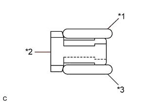
Text in Illustration *1 Upper Side Rail *2 Oil Ring Expander *3 Lower Side Rail Install the oil ring expander and 2 side rails by hand.
Note
When installing the upper side rail and lower side rail, the ends of the oil ring expander may overlap. If it occurs, the upper side rail or lower side rail may move out of its groove.
-
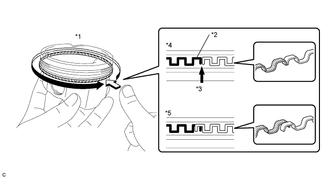
Check that the ends of the oil ring expander are not overlapping and that the upper side rail and lower side rail are securely installed into the groove.
Note
-
After installing the oil ring expander, upper side rail and lower side rail, press around the circumference with a finger to check that they are securely installed into the groove.
-
If the oil ring expander is not securely installed into the groove, check that the ends of the oil ring expander are not overlapping.
-
If the ends of the oil ring expander are overlapping, remove the upper side rail and lower side rail and realign the oil ring expander using a screwdriver.
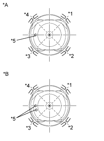
Text in Illustration *1 Press around the circumference *2 Paint (Purple or White) *3 Ring End *4 Correct *5 Incorrect (Ends of the oil ring expander are overlapping) - - -
-
-
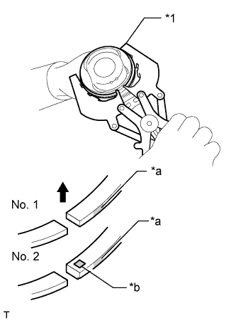
Text in Illustration *1 Piston Ring Expander *a Paint Mark *b Code Mark 
Upward Using a piston ring expander, install the 2 compression rings so that the paint marks are positioned as shown in the illustration.
Note
Install the No. 2 compression ring with the code mark (2N or 2A) facing upward.
-
for 2-piece Type:
-
Text in Illustration *A for TMC Made Engine *B except TMC Made Engine *1 No. 1 and Oil Ring Rail *2 No. 2 and Oil Ring Expander *3 Front Mark Position the piston rings so that the ring ends are as shown in the illustration.
-
-
for 3-piece Type:
-
Text in Illustration *A for TMC Made Engine *B except TMC Made Engine *1 Lower Side Rail *2 No. 2 Compression Ring *3 Upper Side Rail *4 No. 1 Compression Ring and Oil Ring Expander *5 Front Mark Position the piston rings so that the ring ends are as shown in the illustration.
-
-
-
INSTALL CRANKSHAFT BEARING
-
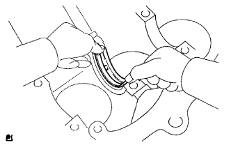
Install the upper bearing with an oil groove on the cylinder block.
Note
Do not apply engine oil to the bearing inner surface or bearing cap contact surfaces.
-
-
INSTALL NO. 2 CRANKSHAFT BEARING
-
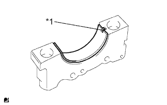
Text in Illustration *1 Claw Install the No. 2 crankshaft bearing on the bearing cap.
Note
Clean the backside of the bearing and the bearing surface of the crankshaft. The surface should be free of dust and oil.
-
-
INSTALL UPPER CRANKSHAFT THRUST WASHER
-
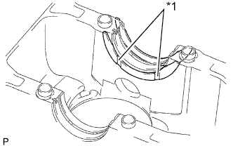
Text in Illustration *1 Oil Groove Install the 2 thrust washers under the No. 3 journal of the cylinder block with the oil grooves facing outward.
Note
Make sure to install the proper thrust washers.
-
Apply engine oil to the crankshaft thrust washers.
-
-
INSTALL CRANKSHAFT
-
Apply engine oil to the upper bearings and place the crankshaft on the cylinder block.
-
Apply engine oil to the lower bearings.
-
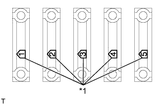
Text in Illustration *1 Front Mark and Number Examine the front marks and install the bearing caps on the cylinder block.
-
Apply a light coat of engine oil to the threads and under the bearing cap bolts.
-
Install the crankshaft bearing cap bolts.
Note
The main bearing cap bolts are tightened in 2 progressive steps.
-
Step 1
-
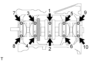
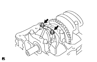
Retighten the 10 main bearing cap bolts in the sequence shown in the illustration.
- Torque:
- 40 N*m { 408 kgf*cm, 30 ft.*lbf }
-
-
Step 2
-
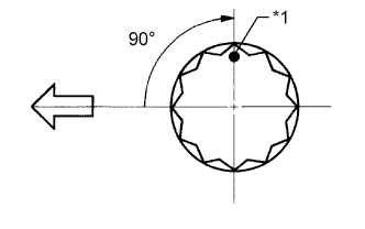
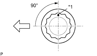
Text in Illustration *1 Paint Mark 
Engine Front Mark the front of the bearing cap bolts with paint.
-
Retighten the bearing cap bolts 90° in the numerical order shown in the illustration.
-
-
Check that the paint mark is now at a 90° angle to the front.
-
Check that the crankshaft turns smoothly.
-
Check the crankshaft thrust clearance Click here.
-
-
INSTALL CONNECTING ROD BEARING
-
Text in Illustration *1 Claw Align the bearing claw with the groove on the connecting rod or connecting cap.
Note
Clean the backside of the bearing and the bearing surface of the connecting rod. The surface should be free of dust and oil.
-
-
INSTALL PISTON SUB-ASSEMBLY WITH CONNECTING ROD
Note
The connecting rod cap bolts are tightened in 2 progressive steps.
-
Apply engine oil to the cylinder walls, pistons, and surfaces of connecting rod bearings.
-
for 2-piece Type:
-
Text in Illustration *A for TMC Made Engine *B except TMC Made Engine *1 No. 1 and Oil Ring Rail *2 No. 2 and Oil Ring Expander *3 Front Mark Check the position of the piston ring ends.
-
-
for 3-piece Type:
-
Text in Illustration *A for TMC Made Engine *B except TMC Made Engine *1 Lower Side Rail *2 No. 2 Compression Ring *3 Upper Side Rail *4 No. 1 Compression Ring and Oil Ring Expander *5 Front Mark Check the position of the piston ring ends.
-
Confirm that the ends of the oil ring expander are not overlapping and that the upper side rail and lower side rail are securely installed into the groove.
Note
-
After installing the oil ring expander, upper side rail and lower side rail, press around the circumference with a finger to check that they are securely installed into the groove.
-
If the oil ring expander is not securely installed into the groove, check that the ends of the oil ring expander are not overlapping.
-
If the ends of the oil ring expander are overlapping, remove the upper side rail and lower side rail and realign the oil ring expander using a screwdriver.
Text in Illustration *1 Press around the circumference *2 Paint (Purple or White) *3 Ring End *4 Correct *5 Incorrect (Ends of the oil ring expander are overlapping) - - -
-
-
for 2-piece Type:
-
Text in Illustration *A for TMC Made Engine *B except TMC Made Engine *1 Front Mark Front Using a piston ring compressor, push the correctly numbered piston and connecting rod assemblies into each cylinder with the front mark of the piston facing forward.
Note
Match the numbered connecting rod cap with the connecting rod.
-
-
for 3-piece Type:
-
Text in Illustration *A for TMC Made Engine *B except TMC Made Engine *1 Front Mark Front Using a piston ring compressor, push the correctly numbered piston and connecting rod assemblies into each cylinder with the front mark of the piston facing forward.
Note
Match the numbered connecting rod cap with the connecting rod.
-
-
Check that the protrusion on the connecting rod cap is facing in the correct direction.
-
Apply a light coat of engine oil to the threads and under the heads of the connecting rod cap bolts.
-
Install the connecting rod cap bolts.
Note
The connecting rod cap bolts should be tightened in 2 progressive steps.
-
Step 1
-
Install and alternately tighten the bolts of the connecting rod cap in several steps.
- Torque:
- 25 N*m { 250 kgf*cm, 18 ft.*lbf }
-
-
Step 2
-
Text in Illustration *1 Paint Mark Engine Front Mark the front of the connecting rod cap bolts with paint.
-
Retighten the cap bolts 90° as shown in the illustration.
-
-
Check that the crankshaft turns smoothly.
-
Check the connecting rod thrust clearance Click here.
-