CYLINDER BLOCK INSPECTION

Tech Tips
Check whether the engine is TMC made or not by referring to the following illustration.
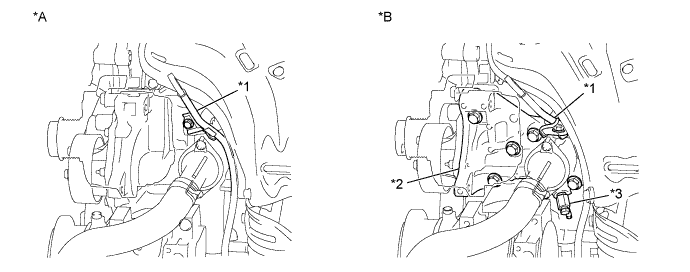
| *A | for TMC Made Engine | *B | except TMC Made Engine |
| *1 | Engine Oil Level Dipstick Guide | *2 | Water Inlet Housing |
| *3 | Water Inlet Housing Drain Cock Assembly | - | - |
-
INSPECT CONNECTING ROD THRUST CLEARANCE
-
Install the connecting rod cap Click here.
-
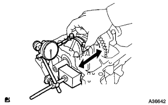
Using a dial indicator, measure the thrust clearance while moving the connecting rod back and forth.
Standard thrust clearance 0.160 to 0.362 mm (0.00630 to 0.0143 in.) Maximum thrust clearance 0.362 mm (0.0143 in.) If the thrust clearance is greater than the maximum, replace the connecting rod assemblies as necessary. If necessary, replace the crankshaft.
-
-
INSPECT CONNECTING ROD OIL CLEARANCE
-
Clean the crank pin and bearing.
-
Check the crank pin and bearing for pitting and scratches.
-
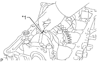
Text in Illustration *1 Plastigage Lay a strip of Plastigage on the crank pin.
-

Text in Illustration *1 Front Mark Check that the front mark of the connecting rod cap is facing forward.
-
Install the connecting rod cap Click here.
Note
Do not turn the crankshaft.
-
Remove the 2 bolts and connecting rod cap Click here.
-
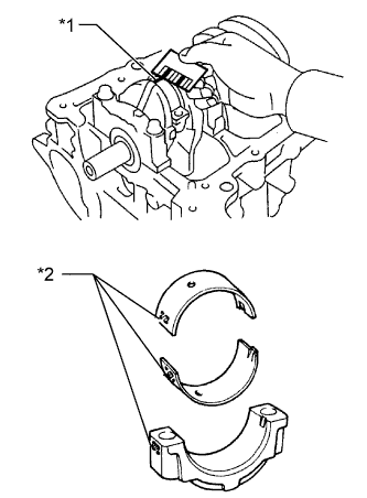
Text in Illustration *1 Plastigage *2 1, 2, or 3 Mark Measure the Plastigage at its widest point.
Standard oil clearance 0.024 to 0.048 mm (0.000945 to 0.00189 in.) Maximum oil clearance 0.08 mm (0.00315 in.) Note
Completely remove the Plastigage after the measurement.
If the oil clearance is greater than the maximum, replace the connecting rod bearings. If necessary, inspect the crankshaft.
Tech Tips
If replacing a bearing, replace it with one that has the same number as its respective connecting rod cap. Each bearing's standard thickness is indicated by a 1, 2, or 3 mark on its surface.
Standard Connecting Rod Large End Bore Diameter Mark Specified Condition Mark 1 51.000 to 51.007 mm (2.0079 to 2.0082 in.) Mark 2 51.008 to 51.013 mm (2.0082 to 2.0084 in.) Mark 3 51.014 to 51.020 mm (2.0084 to 2.0087 in.) Standard Connecting Rod Bearing Thickness Mark Specified Condition Mark 1 1.485 to 1.488 mm (0.0585 to 0.0586 in.) Mark 2 1.489 to 1.491 mm (0.0586 to 0.0587 in.) Mark 3 1.492 to 1.494 mm (0.0587 to 0.0588 in.) Standard crankshaft pin diameter 47.990 to 48.000 (1.8894 to 1.8898 in.)
-
-
INSPECT CYLINDER BLOCK FOR WARPAGE
-
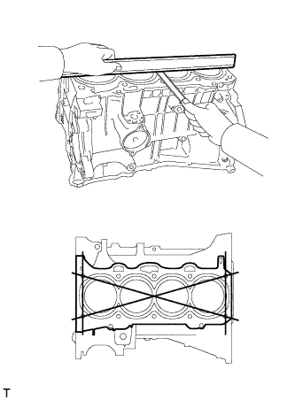
Using a precision straightedge and feeler gauge, measure the warpage of the surface that contacts the cylinder head gasket.
Maximum warpage 0.05 mm (0.00197 in.) If the warpage is greater than the maximum, replace the cylinder block.
-
-
INSPECT CYLINDER BORE
-
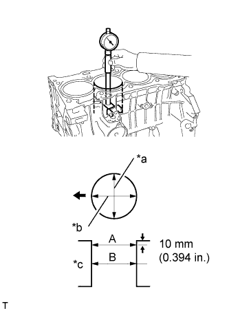
Text in Illustration *a Thrust Direction *b Axial Direction *c Center 
Front Using a cylinder gauge, measure the cylinder bore diameter at positions A and B in the thrust and axial directions.
Standard diameter 88.500 to 88.513 mm (3.4843 to 3.4847 in.) Maximum diameter 88.633 mm (3.4894 in.) If the average diameter of the 4 positions is greater than the maximum, replace the cylinder block.
-
-
INSPECT PISTON
-
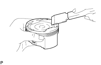
Using a gasket scraper, remove the carbon from the top of the piston.
Note
Do not damage the piston.
-

Using a groove cleaning tool or a broken ring, clean the piston ring grooves.
-
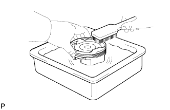
Using a brush and solvent, thoroughly clean the piston.
Note
Do not use a wire brush.
-
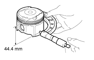
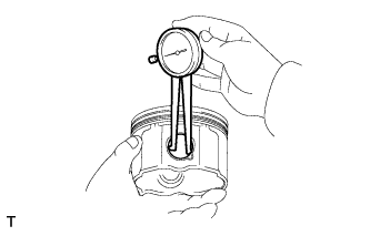
Using a micrometer, measure the piston diameter at right angles to the piston pin hole, and at the piston 44.4 mm (1.748 in.) from the piston head.
Standard piston diameter 88.469 to 88.479 mm (3.4830 to 3.4834 in.) If the diameter is not as specified, replace the piston.
-
-
INSPECT PISTON OIL CLEARANCE
-
Subtract the piston diameter measurement from the cylinder bore diameter measurement.
Standard oil clearance 0.021 to 0.044 mm (0.000827 to 0.00173 in.) Maximum oil clearance 0.10 mm (0.00394 in.) If the oil clearance is greater than the maximum, replace all the pistons. If necessary, replace the cylinder block.
-
-
INSPECT RING GROOVE CLEARANCE
-
for 2-piece Type:
-
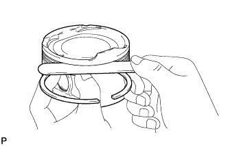
Using a feeler gauge, measure the clearance between a new piston ring and the wall of the ring groove.
Standard Ring Groove Clearance Item Specified Condition No. 1 Ring 0.020 to 0.070 mm (0.000787 to 0.00276 in.) No. 2 Ring 0.020 to 0.060 mm (0.000787 to 0.00236 in.) Oil Ring 0.020 to 0.070 mm (0.000787 to 0.00276 in.) If the groove clearance is not as specified, replace the piston.
-
-
for 3-piece Type:
-
Using a feeler gauge, measure the clearance between a new piston ring and the wall of the ring groove.
Standard Ring Groove Clearance Item Specified Condition No. 1 Ring 0.020 to 0.070 mm (0.000787 to 0.00276 in.) No. 2 Ring 0.020 to 0.060 mm (0.000787 to 0.00236 in.) Oil Ring 0.060 to 0.120 mm (0.00236 to 0.00472 in.) If the groove clearance is not as specified, replace the piston.
-
-
-
INSPECT PISTON RING END GAP
-
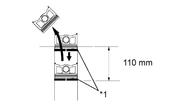
Text in Illustration *1 Piston Ring Using a piston, push the piston ring a little beyond the bottom of the ring travel, 110 mm (4.33 in.) from the top of the cylinder block.
-
Using a feeler gauge, measure the end gap.
Standard End Gap Item Specified Condition No. 1 Ring 0.24 to 0.31 mm (0.00945 to 0.0122 in.) No. 2 Ring
(2-piece Type)
0.33 to 0.43 mm (0.0130 to 0.0169 in.) No. 2 Ring
(3-piece Type)
0.49 to 0.59 mm (0.0193 to 0.0232 in.) Oil Ring
(2-piece Type)
0.10 to 0.20 mm (0.00394 to 0.00787 in.) Oil Ring
(3-piece Type)
0.10 to 0.35 mm (0.00394 to 0.0138 in.) Maximum End Gap Item Specified Condition No. 1 Ring 0.89 mm (0.0350 in.) No. 2 Ring
(2-piece Type)
1.37 mm (0.0539 in.) No. 2 Ring
(3-piece Type)
1.53 mm (0.0602 in.) Oil Ring
(2-piece Type)
0.73 mm (0.0287 in.) Oil Ring
(3-piece Type)
0.73 mm (0.0287 in.) If the end gap is greater than the maximum, replace the piston ring. If the end gap is greater than the maximum with a new piston ring, replace the cylinder block.
-
-
INSPECT PISTON PIN OIL CLEARANCE
-
Using a caliper gauge, measure the piston pin bore diameter.
Standard piston pin bore diameter 22.001 to 22.010 mm (0.8662 to 0.8665 in.) Item Specified Condition A 22.001 to 22.004 mm (0.8662 to 0.8663 in.) B 22.005 to 22.007 mm (0.8663 to 0.8664 in.) C 22.008 to 22.010 mm (0.8665 to 0.8665 in.) If the diameter is not as specified, replace the piston.
-
Using a micrometer, measure the piston pin diameter.
Standard piston pin diameter 21.997 to 22.006 mm (0.8660 to 0.8664 in.) Item Specified Condition A 21.997 to 22.000 mm (0.8660 to 0.8661 in.) B 22.001 to 22.003 mm (0.8662 to 0.8663 in.) C 22.004 to 22.006 mm (0.8663 to 0.8664 in.) If the diameter is not as specified, replace the piston pin.
-
Using a caliper gauge, measure the connecting rod small end bore diameter.
Standard connecting rod small end bore diameter 22.005 to 22.014 mm (0.8663 to 0.8667 in.) Item Specified Condition A 22.005 to 22.008 mm (0.8663 to 0.8665 in.) B 22.009 to 22.011 mm (0.8665 to 0.8666 in.) C 22.012 to 22.014 mm (0.8666 to 0.8667 in.) If the diameter is not as specified, replace the connecting rod.
-
for 2-piece Type:
-
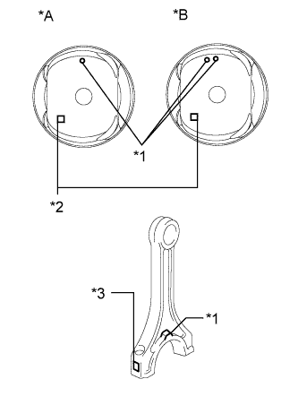
Text in Illustration *A except TMC Made Engine *B for TMC Made Engine *1 Front Mark *2 Piston Pin Bore Diameter Mark *3 Connecting Rod Small End Bore Diameter Mark Subtract the piston pin diameter measurement from the piston pin bore diameter measurement.
Standard oil clearance 0.001 to 0.007 mm (0.0000394 to 0.000276 in.) Maximum oil clearance 0.010 mm (0.000394 in.) If the oil clearance is greater than the maximum, replace the connecting rod. If necessary, replace the piston and piston pin as a set.
-
Subtract the piston pin diameter measurement from the connecting rod small end bore diameter measurement.
Standard oil clearance 0.005 to 0.011 mm (0.000197 to 0.000433 in.) Maximum oil clearance 0.011 mm (0.000433 in.) If the oil clearance is greater than the maximum, replace the connecting rod. If necessary, replace the connecting rod and piston pin as a set.
-
-
for 3-piece Type:
-
Text in Illustration *A for TMC Made Engine *B except TMC Made Engine *1 Front Mark *2 Piston Pin Bore Diameter Mark *3 Connecting Rod Small End Bore Diameter Mark Subtract the piston pin diameter measurement from the piston pin bore diameter measurement.
Standard oil clearance 0.001 to 0.007 mm (0.0000394 to 0.000276 in.) Maximum oil clearance 0.010 mm (0.000394 in.) If the oil clearance is greater than the maximum, replace the connecting rod. If necessary, replace the piston and piston pin as a set.
-
Subtract the piston pin diameter measurement from the connecting rod small end bore diameter measurement.
Standard oil clearance 0.005 to 0.011 mm (0.000197 to 0.000433 in.) Maximum oil clearance 0.011 mm (0.000433 in.) If the oil clearance is greater than the maximum, replace the connecting rod. If necessary, replace the connecting rod and piston pin as a set.
-
-
-
INSPECT CONNECTING ROD BOLT
-
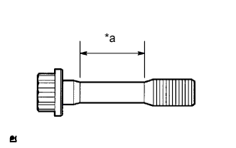
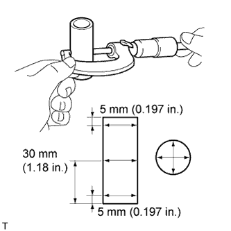
Text in Illustration *a Measurement Area Using a vernier caliper, measure the diameter of the bolt in the area shown in the illustration.
Standard diameter 7.2 to 7.3 mm (0.283 to 0.287 in.) Minimum diameter 7.0 mm (0.276 in.) Tech Tips
-
Diameter measurements should be done at several points.
-
If the diameter is less than the minimum, replace the bolt with a new one. Failure to do so may lead to engine damage.
-
If there is any thread deformation, replace the bolt with a new one.
-
-
-
INSPECT CONNECTING ROD SUB-ASSEMBLY
-
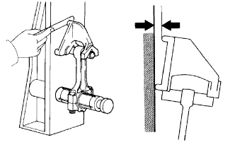
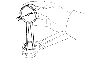
Using a connecting rod aligner and feeler gauge, check the connecting rod alignment.
-
Check for misalignment.
Maximum misalignment 0.05 mm (0.00197 in.) per 100 mm (3.94 in.) If the misalignment is greater than the maximum, replace the connecting rod.
-
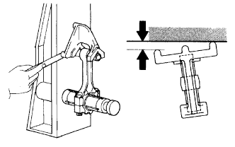
Check for twist.
Maximum twist 0.15 mm (0.00591 in.) per 100 mm (3.94 in.) If the twist is greater than the maximum, replace the connecting rod.
-
-
-
INSPECT CRANKSHAFT
-
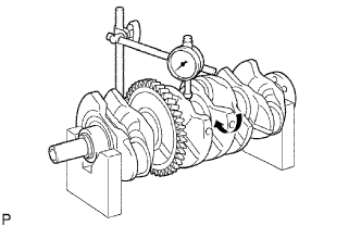
Using a dial indicator and V-blocks, measure the circle runout as shown in the illustration.
Maximum circle runout 0.03 mm (0.00118 in.) If the circle runout is greater than the maximum, replace the crankshaft.
-
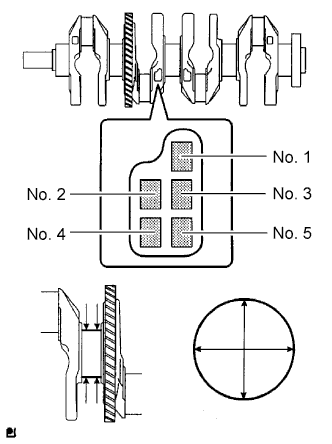
Using a micrometer, measure the diameter of each main journal.
Standard diameter 54.988 to 55.000 mm (2.1649 to 2.1654 in.) If the diameter is not as specified, check the crankshaft oil clearance.
-
Check each main journal for taper and distortion as shown in the illustration.
Maximum taper and distortion 0.003 mm (0.000118 in.) If the taper and distortion are greater than the maximum, replace the crankshaft.
Standard Diameter (Reference) Mark Specified Condition 0 54.999 to 55.000 mm (2.16531 to 2.16535 in.) 1 54.997 to 54.998 mm (2.16523 to 2.16527 in.) 2 54.995 to 54.996 mm (2.16515 to 2.16519 in.) 3 54.993 to 54.994 mm (2.16507 to 2.16511 in.) 4 54.991 to 54.992 mm (2.16500 to 2.16503 in.) 5 54.988 to 54.990 mm (2.1649 to 2.1650 in.) -
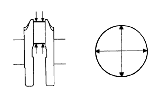
Using a micrometer, measure the diameter of each crank pin.
Standard diameter 47.990 to 48.000 mm (1.8894 to 1.8898 in.) If the diameter is not as specified, check the connecting rod oil clearance.
-
Inspect each crank pin for taper and distortion as shown in the illustration.
Maximum taper and distortion 0.003 mm (0.000118 in.) If the taper and distortion are greater than the maximum, replace the crankshaft.
-
-
INSPECT CRANKSHAFT THRUST CLEARANCE
-
Install the main bearing cap Click here.
-
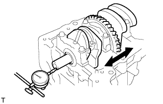
Using a dial indicator, measure the thrust clearance while prying the crankshaft back and forth with a screwdriver.
Standard thrust clearance 0.04 to 0.24 mm (0.00157 to 0.00945 in.) Maximum thrust clearance 0.30 mm (0.0118 in.) If the thrust clearance is greater than the maximum, replace the thrust washers as a set.
Tech Tips
The thrust washer thickness is 1.93 to 1.98 mm (0.0760 to 0.0780 in.).
-
-
INSPECT CRANKSHAFT OIL CLEARANCE
-
Check the crank journal and bearing for pitting and scratches.
-
Install the crankshaft bearing Click here.
-
Place the crankshaft on the cylinder block.
-
Text in Illustration *1 Plastigage Lay a strip of Plastigage across each journal.
-
Examine the front marks and numbers and install the bearing caps on the cylinder block.
Tech Tips
A number is marked on each main bearing cap to indicate the installation position.
-
Install the main bearing caps Click here.
Note
Do not turn the crankshaft.
-
Remove the main bearing caps Click here.
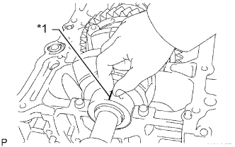
-
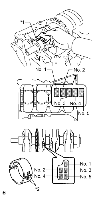
Text in Illustration *1 Plastigage *2 Number Mark Measure the Plastigage at its widest point.
Standard oil clearance 0.008 to 0.024 mm (0.000315 to 0.000945 in.) Maximum oil clearance 0.05 mm (0.00197 in.) Note
Remove the Plastigage completely after the measurement.
If the oil clearance is greater than the maximum, replace the crankshaft bearing. If necessary, replace the crankshaft.
Tech Tips
-
If replacing a bearing, select a new one with the same number. If the number of the bearing cannot be determined, calculate the correct bearing number by adding together the numbers imprinted on the cylinder block and crankshaft. Then select a new bearing with the calculated number. There are 4 sizes of standard bearings, marked "1", "2", "3" and "4" accordingly.
-
EXAMPLE: Cylinder block "3" + Crankshaft "5" = Total number 8 (Use bearing "3")
Cylinder block + Crankshaft 0 to 2 3 to 5 6 to 8 9 to 11 Bearing to be used "1" "2" "3" "4" Standard Cylinder Block Journal Bore Diameter Mark Specified Condition 0 59.000 to 59.002 mm (2.32283 to 2.32291 in.) 1 59.003 to 59.004 mm (2.32295 to 2.32299 in.) 2 59.005 to 59.006 mm (2.32303 to 2.32307 in.) 3 59.007 to 59.009 mm (2.32311 to 2.32318 in.) 4 59.010 to 59.011 mm (2.32322 to 2.32326 in.) 5 59.012 to 59.013 mm (2.32330 to 2.32334 in.) 6 59.014 to 59.016 mm (2.32338 to 2.32346 in.) Standard Crankshaft Journal Diameter Mark Specified Condition 0 54.999 to 55.000 mm (2.16531 to 2.16535 in.) 1 54.997 to 54.998 mm (2.16523 to 2.16527 in.) 2 54.995 to 54.996 mm (2.16515 to 2.16519 in.) 3 54.993 to 54.994 mm (2.16507 to 2.16511 in.) 4 54.991 to 54.992 mm (2.16500 to 2.16504 in.) 5 54.988 to 54.990 mm (2.16488 to 2.16496 in.) Standard Bearing Center Wall Thickness Mark Specified Condition 1 1.993 to 1.996 mm (0.078464 to 0.078583 in.) 2 1.997 to 1.999 mm (0.078622 to 0.078701 in.) 3 2.000 to 2.002 mm (0.078740 to 0.078819 in.) 4 2.003 to 2.005 mm (0.078858 to 0.078937 in.) -
-
-
INSPECT CRANKSHAFT BEARING CAP SET RING PIN
-
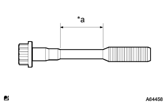
Text in Illustration *a Measurement Area Using a vernier caliper, measure the diameter of the bolt in the area shown in the illustration.
Standard diameter 7.5 to 7.6 mm (0.295 to 0.299 in.) Minimum diameter 7.5 mm (0.295 in.) Tech Tips
-
Diameter measurements should be done at several points.
-
If the diameter is less than the minimum, replace the bolt with a new one. Failure to do so may lead to engine damage.
-
If there is any thread deformation, replace the bolt with a new one.
-
-