CYLINDER HEAD REASSEMBLY

-
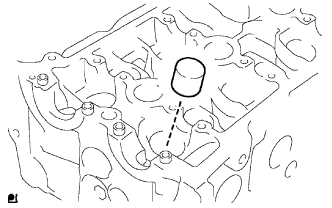
INSTALL RING PIN
-
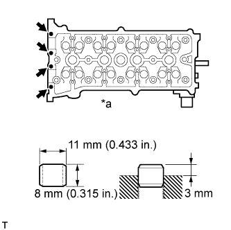
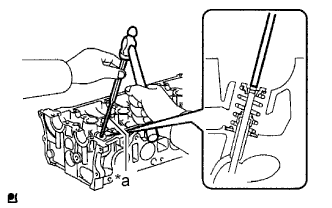
Text in Illustration *a Upper Side Using a plastic-faced hammer, tap in a new ring pin to the specified protrusion height.
Standard protrusion height 3 mm (0.118 in.)
-
-
INSTALL STUD BOLT
Note
If any of the stud bolts is deformed or the threads are damaged, replace it.
-
Using E5 and E7 "TORX" sockets, install the stud bolts.
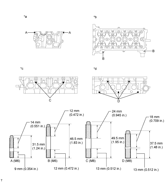
Text in Illustration *a Front Side *b Upper Side *c Intake Side *c Exhaust Side - Torque:
- Bolt A
- 5.0 N*m { 51 kgf*cm, 44 in.*lbf }
- Bolt B
- 5.0 N*m { 51 kgf*cm, 44 in.*lbf }
- Bolt C
- 9.5 N*m { 97 kgf*cm, 84 in.*lbf }
- Bolt D
- 9.5 N*m { 97 kgf*cm, 84 in.*lbf }
-
-
INSTALL NO. 1 STRAIGHT HEAD SCREW PLUG
-
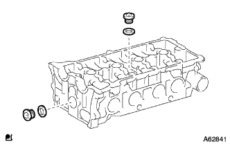
Using a 14 mm straight hexagon wrench, install 2 new gaskets and the 2 straight screw plugs.
- Torque:
- 86 N*m { 877 kgf*cm, 64 ft.*lbf }
-
-
INSTALL VALVE SPRING SEAT
-
Install the valve spring seats into the cylinder head.
-
-
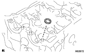
INSTALL VALVE STEM OIL SEAL
-
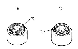
Text in Illustration *a Intake Side *b Exhaust Side *c Gray *d Black Apply a light coat of engine oil to a new oil seal.
Note
Pay close attention when installing the intake and exhaust oil seals. Installing the intake oil seal into the exhaust side or installing the exhaust oil seal into the intake side may cause installation problems later.
Tech Tips
The intake valve oil seal is gray and the exhaust valve oil seal is black.
-
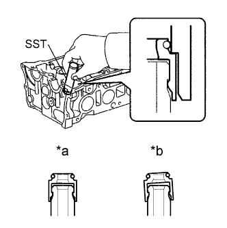
Text in Illustration *a CORRECT *b INCORRECT Using SST, push in the oil seal.
- SST
- 09201-41020
Note
Failure to use SST will cause the seal to be damaged or improperly seated.
-
-
INSTALL INTAKE VALVE
-
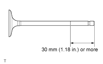
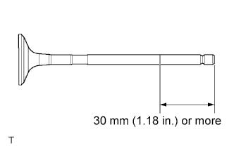
Apply a sufficient coat of engine oil to the tip area of the intake valve shown in the illustration.
-
Install the valve, compression spring and spring retainer to the cylinder head.
Note
Install the same parts in the same combination to the original locations.
-
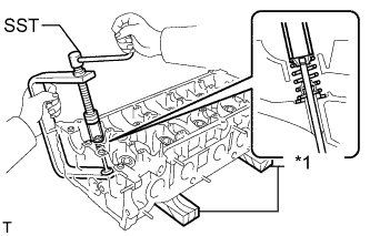
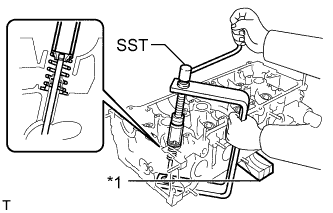
Text in Illustration *1 Wooden Block Using SST and wooden blocks, compress the spring and install the 2 retainer locks.
- SST
- 09202-70020 ( 09202-00010 )
-
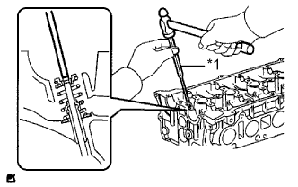
Text in Illustration *1 5 mm Pin Punch Using a 5 mm pin punch and plastic hammer, lightly tap the valve stem tip to ensure a proper fit.
Note
Be careful not to damage the valve stem tip.
-
-
INSTALL EXHAUST VALVE
-
Apply a sufficient coat of engine oil to the tip area of the exhaust valve shown in the illustration.
-
Install the valve, compression spring and spring retainer to the cylinder head.
Note
Install the same parts in the same combination to the original locations.
-
Text in Illustration *1 Wooden Block Using SST and wooden blocks, compress the spring and install the 2 retainer locks.
- SST
- 09202-70020 ( 09202-00010 )
-
Text in Illustration *a 5 mm Pin Punch Using a 5 mm pin punch and plastic hammer, lightly tap the valve stem tip to ensure a proper fit.
Note
Be careful not to damage the valve stem tip.
-
-
INSTALL VALVE LIFTER
-
Apply a light coat of engine oil.
-
Assemble the valve lifter and the tip of the valve stem.
Note
Install the same parts in the same combination to the original locations.
-