ENGINE UNIT INSTALLATION

Tech Tips
Check whether the engine is TMC made or not by referring to the following illustration.
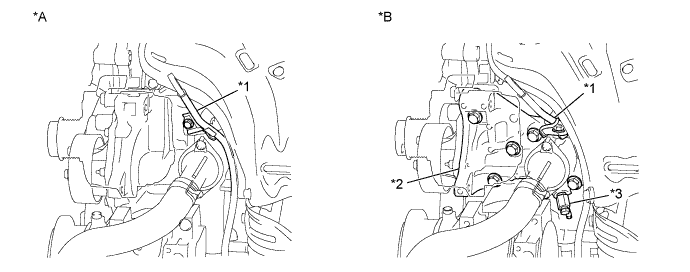
| *A | for TMC Made Engine | *B | except TMC Made Engine |
| *1 | Engine Oil Level Dipstick Guide | *2 | Water Inlet Housing |
| *3 | Water Inlet Housing Drain Cock Assembly | - | - |
-
INSTALL STUD BOLT
-
Using a socket wrench (8 mm), install the stud bolt to the engine mounting bracket RH.
- Torque:
- 10 N*m { 102 kgf*cm, 7 ft.*lbf }
-
-
INSTALL RADIO SETTING CONDENSER
-
Install the radio setting condenser with the bolt.
- Torque:
- 10 N*m { 102 kgf*cm, 7 ft.*lbf }
-
-
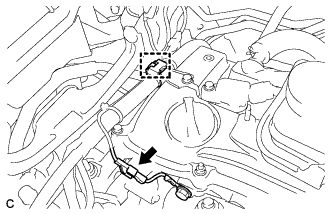
INSTALL ENGINE COOLANT TEMPERATURE SENSOR
-
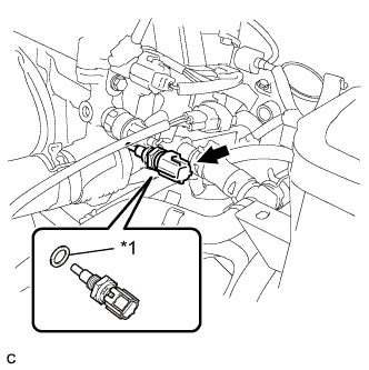
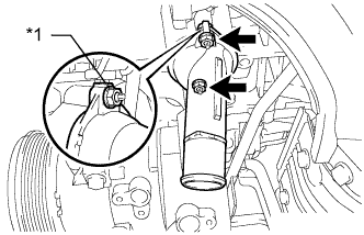
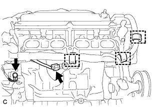
Text in Illustration *1 New Gasket Install the engine coolant temperature sensor through a new gasket.
- Torque:
- 20 N*m { 204 kgf*cm, 15 ft.*lbf }
-
Connect the engine coolant temperature sensor connector.
-
-
INSTALL OIL PRESSURE SWITCH
-
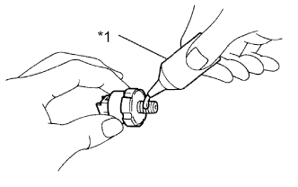
Text in Illustration *1 Adhesive Apply adhesive to 2 or 3 threads of the oil pressure switch assembly.
Adhesive Toyota Genuine Adhesive 1344, Three Bond 1344 or equivalent -
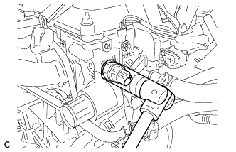
Using a 24 mm deep socket wrench, install the oil pressure switch assembly.
- Torque:
- 15 N*m { 153 kgf*cm, 11 ft.*lbf }
Note
Do not start the engine within 1 hour of installation.
-
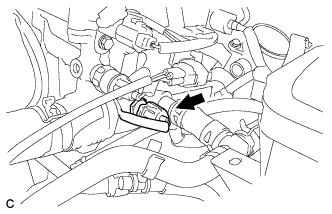
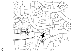
Connect the oil pressure switch connector.
-
-
INSTALL KNOCK SENSOR
-
Install the knock control sensor with the nut.
- Torque:
- 20 N*m { 204 kgf*cm, 15 ft.*lbf }
-
Connect the sensor connector.
-
-
INSTALL IGNITION COIL ASSEMBLY
-
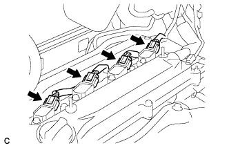
Install the 4 ignition coils with the 4 bolts.
- Torque:
- 9.0 N*m { 92 kgf*cm, 80 in.*lbf }
-
Connect the 4 ignition coil connectors.
-
-
INSTALL UNION BOLT (for TMC Made Engine with Engine Oil Cooler)
-
Apply adhesive to the threads of the union bolt.
Adhesive Toyota Genuine Adhesive 1324, Three Bond 1324 or equivalent -
Install the union bolt.
- Torque:
- 25 N*m { 255 kgf*cm, 18 ft.*lbf }
-
-
INSTALL OIL COOLER PIPE (for TMC Made Engine with Engine Oil Cooler)
-
for Automatic Transaxle:
-
Install a new gasket and the oil cooler pipe with the bolt and 2 nuts.
- Torque:
- 9.0 N*m { 92 kgf*cm, 80 in.*lbf }
-
-
-
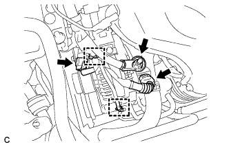
INSTALL NO. 3 WATER BY-PASS HOSE (for TMC Made Engine with Engine Oil Cooler)
-
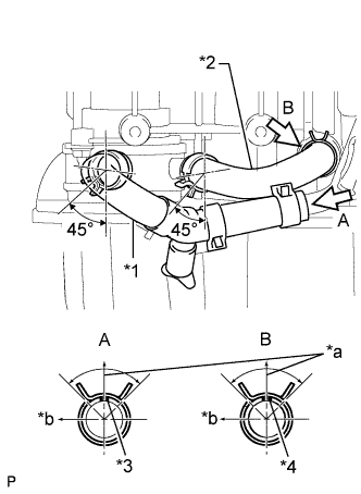
Text in Illustration *1 No. 3 Water By-pass Hose *2 No. 4 Water By-pass Hose *3 Yellow Paint Mark *4 White Paint Mark *a Top *b LH Side Connect the No. 3 water by-pass hose.
-
-
INSTALL NO. 4 WATER BY-PASS HOSE (for TMC Made Engine with Engine Oil Cooler)
-
Connect the No. 4 water by-pass hose.
-
-
INSTALL NO. 3 WATER BY-PASS PIPE (for CVT)
-
Install a new gasket and the No. 3 water by-pass pipe with the bolt and 2 nuts.
- Torque:
- 9.0 N*m { 92 kgf*cm, 80 in.*lbf }
-
-
INSTALL NO. 1 WATER BY-PASS PIPE
-
Install a new gasket and the No. 1 water by-pass pipe with the bolt and 2 nuts.
- Torque:
- 9.0 N*m { 92 kgf*cm, 80 in.*lbf }
-
-
INSTALL ENGINE OIL LEVEL DIPSTICK GUIDE
-
Install a new O-ring and the engine oil level dipstick guide with the bolt.
- Torque:
- 9.0 N*m { 92 kgf*cm, 80 in.*lbf }
-
-
INSTALL ENGINE OIL LEVEL DIPSTICK
-
Install the engine oil level dipstick.
-
-
INSTALL NO. 4 WATER BY-PASS PIPE (for TMC Made Engine with Engine Oil Cooler)
-
for CVT:
-
Install the No. 4 water by-pass pipe with the bolt and nut.
- Torque:
- 9.0 N*m { 92 kgf*cm, 80 in.*lbf }
-
-
-
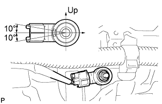
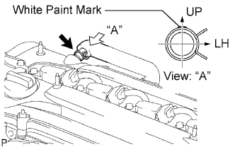
INSTALL THERMOSTAT
-
Position a new gasket onto the thermostat.
-
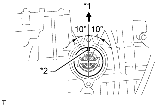
Text in Illustration *1 Upward *2 Jiggle Valve Install the thermostat with the jiggle valve upward.
Tech Tips
The jiggle valve may be set to within 10° on either side of the indicated position.
-
-
INSTALL WATER INLET
-
Text in Illustration *1 Mark Install the water inlet with the mark upward.
-
Install the water inlet with the 2 nuts.
- Torque:
- 9.0 N*m { 92 kgf*cm, 80 in.*lbf }
-
-
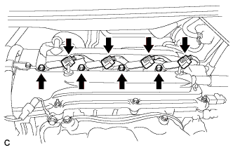
INSTALL EXHAUST MANIFOLD CONVERTER SUB-ASSEMBLY
-
Install a new exhaust manifold to head gasket.
-
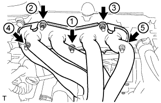
Using a 12 mm deep socket wrench, install the exhaust manifold converter sub-assembly and 5 nuts in the order shown in the illustration.
- Torque:
- 37 N*m { 377 kgf*cm, 27 ft.*lbf }
-
-
INSTALL NO. 2 MANIFOLD STAY
-
Install the No. 2 manifold stay with the bolt and nut.
- Torque:
- 44 N*m { 449 kgf*cm, 33 ft.*lbf }
-
-
INSTALL MANIFOLD STAY
-
Install the manifold stay with the bolt and nut.
- Torque:
- 44 N*m { 449 kgf*cm, 33 ft.*lbf }
-
-
INSTALL NO. 1 EXHAUST MANIFOLD HEAT INSULATOR
-
Install the No. 1 exhaust manifold heat insulator with the 4 bolts.
- Torque:
- 12 N*m { 122 kgf*cm, 9 ft.*lbf }
-
-
INSTALL INTAKE MANIFOLD
-
Install the vacuum hose clamp with the bolt.
- Torque:
- 8.5 N*m { 87 kgf*cm, 75 in.*lbf }
-
Install the union to check valve hose, No. 2 ventilation hose and No. 1 throttle body hose.
-
Install the No. 1 intake manifold insulator.
-
Install a new No. 1 intake manifold to head gasket.
-
Set the intake manifold.
-
Connect the engine wire.
-
Connect the engine wire harness with the 2 bolts.
-
Connect the connector and wire harness clamp.
-
Install the earth bolt.
- Torque:
- 8.4 N*m { 86 kgf*cm, 74 in.*lbf }
-
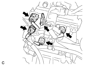
Connect the 4 connectors.
-
Connect the 4 connectors.
-
Install the earth bolt.
- Torque:
- 8.4 N*m { 86 kgf*cm, 74 in.*lbf }
-
Connect the connector and 3 wire harness clamps.
-
Connect the earth connector and wire harness clamp.
-
Connect the terminal B with the nut and install the terminal cap.
- Torque:
- 9.8 N*m { 100 kgf*cm, 87 in.*lbf }
-
Connect the 2 connectors and 2 wire harness clamps.
-
Connect the compressor connector and clamp.
-
-
Using an E7 "TORX" wrench, install the 2 stud bolts.
- Torque:
- 9.5 N*m { 97 kgf*cm, 84 in.*lbf }
-
Install the intake manifold with the 5 bolts and 2 nuts.
- Torque:
- 30 N*m { 306 kgf*cm, 22 ft.*lbf }
-
Connect the union to check valve hose to the hose clamp.
-
Connect the oxygen sensor connector and clamp.
-
-
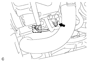
CONNECT NO. 2 VENTILATION HOSE
-
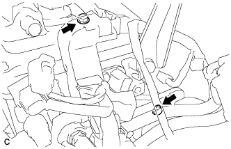
Connect the ventilation hose to the ventilation valve.
Note
Make sure that the paint mark and hose clamp are positioned as shown in the illustration after connecting the hose.
-
-
INSTALL FUEL INJECTOR ASSEMBLY
-
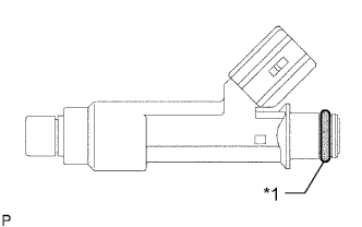
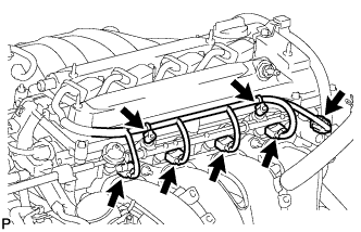
Text in Illustration *1 O-ring Apply a light coat of gasoline or spindle oil to new O-rings, then install them to each fuel injector.
-
Apply a light coat of gasoline or spindle oil to the part of the fuel delivery pipe which comes into contact with the O-ring of the fuel injector.
-
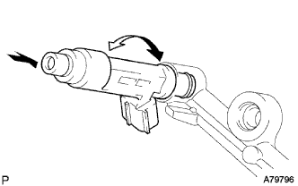
Push and twist each fuel injector to install them into the fuel delivery pipe.
Note
Make sure that the O-ring is not cracked or jammed before installing the injector.
-
Check that the fuel injector rotates smoothly. If the fuel injector does not rotate, replace the O-ring.
-
-
INSTALL FUEL DELIVERY PIPE SUB-ASSEMBLY
-
Install 4 new insulators into the cylinder head.
-
Install the 2 delivery pipe spacers onto the cylinder head.
-
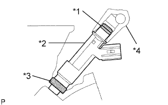
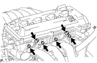
Text in Illustration *1 O-ring *2 Fuel Injector *3 Insulator *4 Fuel Delivery Pipe Install the fuel delivery pipe together with the 4 fuel injectors, then temporarily tighten the 2 bolts.
Note
Be careful not to drop the fuel injectors when installing the fuel delivery pipe.
-
Check that the fuel injector rotates smoothly.
If the fuel injector does not rotate smoothly, replace the O-ring.
-
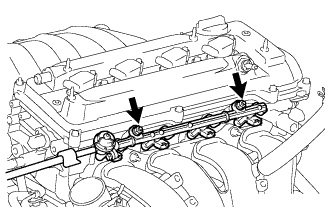
Tighten the 2 bolts to the specified torque.
- Torque:
- 20 N*m { 204 kgf*cm, 15 ft.*lbf }
-
Connect the 4 fuel injector connectors.
-
Connect the oil control valve connector.
-
Install the 2 wire harness clamps.
-
-
INSTALL THROTTLE BODY ASSEMBLY
-
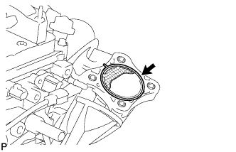
Install a new gasket onto the intake manifold.
-
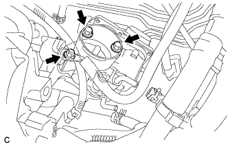
Temporarily install the throttle body assembly and fuel pipe support bracket with the 3 bolts.
-
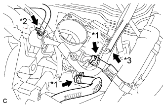
Connect the 2 water by-pass hoses. (*1).
-
Connect the purge line hose. (*2)
-
Connect the No. 1 throttle body hose. (*3)
-
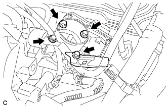
Install the fuel pipe support bracket and throttle body assembly with the 4 bolts.
- Torque:
- 30 N*m { 306 kgf*cm, 22 ft.*lbf }
-
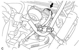
Connect the throttle body connector to the throttle body assembly.
-
Connect the wire harness clamp to the fuel pipe support bracket.
-
Install the hose to the fuel pipe support bracket.
-
-
INSTALL ENGINE WIRE
-
Install the engine wire.
-
-
INSTALL IDLER PULLEY BRACKET
-
Install the idler pulley bracket with the 2 bolts.
- Torque:
- 50 N*m { 510 kgf*cm, 37 ft.*lbf }
-
-
INSTALL DRIVE SHAFT BEARING BRACKET
-
Install the drive shaft bearing bracket with the 3 bolts.
- Torque:
- 64 N*m { 652 kgf*cm, 47 ft.*lbf }
-
-
INSTALL ENGINE HANGERS
-
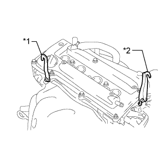
Text in Illustration *1 No. 1 Engine Hanger *2 No. 2 Engine Hanger Install the No. 1 engine hanger and No. 2 engine hanger with the 2 bolts.
- Torque:
- 38 N*m { 387 kgf*cm, 28 ft.*lbf }
Part Name Part No. No. 1 engine hanger 12281-28010 or
12281-0H010
No. 2 engine hanger 12282-28010 or
12282-0H010
Bolt 91552-B1020 or
90105-C0076
-