ENGINE UNIT REASSEMBLY

Tech Tips
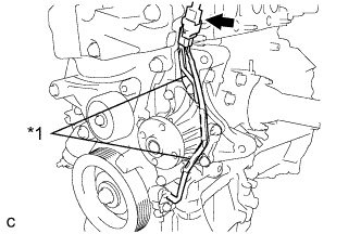
Check whether the engine is TMC made or not by referring to the following illustration.
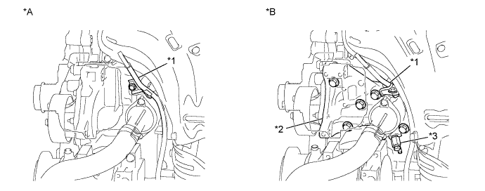
| *A | for TMC Made Engine | *B | except TMC Made Engine |
| *1 | Engine Oil Level Dipstick Guide | *2 | Water Inlet Housing |
| *3 | Water Inlet Housing Drain Cock Assembly | - | - |
-
INSTALL NO. 1 BALANCESHAFT BEARING
-
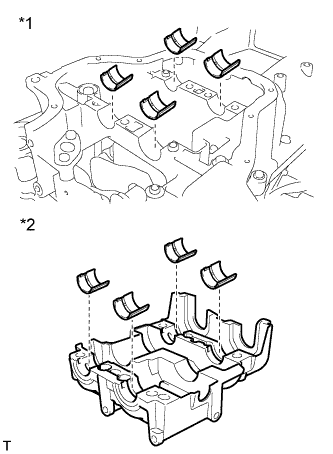
Text in Illustration *1 Stiffening Crankcase *2 Balanceshaft Housing Align the bearing claw with the claw groove, and push in the 8 bearings.
Note
Do not apply engine oil to the contact surfaces of the balanceshaft bearing and balanceshaft housing.
-
Apply a light coat of engine oil to the bearings.
-
-
INSTALL NO. 1 AND NO. 2 BALANCESHAFTS
-
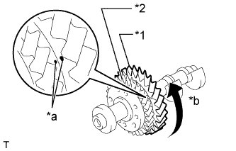
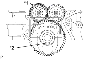
Text in Illustration *1 No. 1 Driven Gear *2 No. 2 Driven Gear *a Matchmark *b Rotating Direction Rotate the No. 1 driven gear of the No. 1 balanceshaft in the rotating direction until it hits the stopper.
Note
Confirm that the matchmarks on the No. 1 and No. 2 driven gears are matched.
-
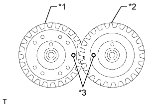
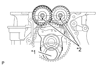
Text in Illustration *1 No. 1 Balanceshaft *2 No. 2 Balanceshaft *3 Alignment Mark Confirm that the alignment marks on the No. 1 and No. 2 balanceshafts are aligned.
-
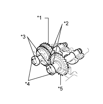
Text in Illustration *1 No. 1 Balanceshaft *2 Alignment Mark *3 Adjusting Hole *4 Timing Mark *5 No. 2 Balanceshaft Align the alignment marks on the No. 1 and No. 2 balanceshafts as shown in the illustration.
-
Place the No. 1 and No. 2 balancshafts onto the crankcase.
-
Apply a light coat of engine oil to the threads and under the heads of the bolts.
-
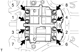
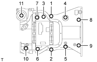
Using several steps, uniformly install and tighten the 8 bolts in the sequence shown in the illustration.
- Torque:
- 22 N*m { 220 kgf*cm, 16 ft.*lbf }
-
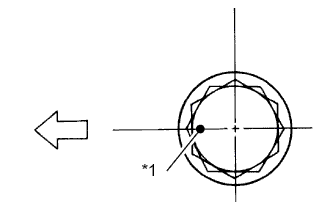
Text in Illustration *1 Paint Mark 
Engine Front Mark the front of the bolts with paint.
-
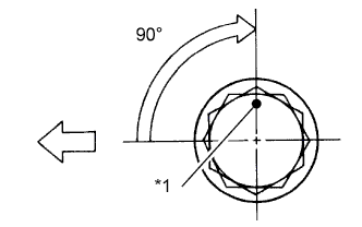
Text in Illustration *1 Paint Mark Engine Front Further tighten the bolts 90° as shown in the illustration.
-
Check that the paint mark is now at a 90° angle to the front.
-
-
INSTALL STIFFENING CRANKCASE ASSEMBLY
-
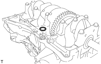
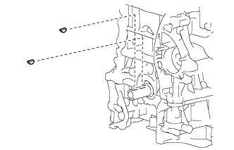
Place a new O-ring on the cylinder block as shown in the illustration.
-
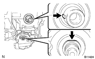
Text in Illustration *1 No. 1 Crank Pin *2 Adjusting Hole With the No. 1 crank pin of the crankshaft placed at the TDC position, install the No. 1 and No. 2 balanceshafts and align the adjusting holes as shown in the illustration.
-
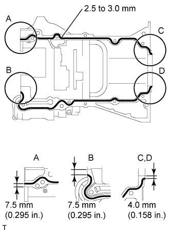
Apply a continuous bead of seal packing (Diameter 2.5 to 3.0 mm (0.0984 to 0.118 in.)) as shown in the illustration.
Seal Packing Toyota Genuine Seal Packing Black, Three Bond 1207B or equivalent Note
-
Remove any oil from the contact surfaces.
-
Install the crankcase within 3 minutes of applying seal packing.
-
Do not add engine oil for at least 2 hours after installing the crankcase.
-
-
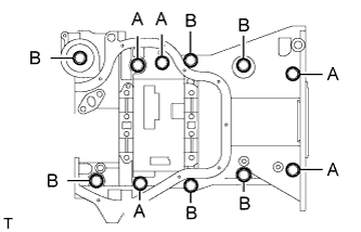
Temporarily install the crankcase with the 11 bolts.
Item Bolt Length A 125 mm (4.92 in.) B 45 mm (1.77 in.) -
Uniformly tighten the bolts.
- Torque:
- 24 N*m { 245 kgf*cm, 18 ft.*lbf }
-
Text in Illustration *1 Timing Mark *2 Key Confirm that the timing marks on the balanceshafts are aligned when the key groove is placed at the TDC position, as shown in the illustration.
-
-
INSTALL OIL PUMP ASSEMBLY
-
Install a new gasket and the oil pump with the 3 bolts.
- Torque:
- 19 N*m { 194 kgf*cm, 14 ft.*lbf }
-
-
INSTALL REAR CRANKSHAFT OIL SEAL
-
Apply MP grease to the lip of a new rear crankshaft oil seal.
-
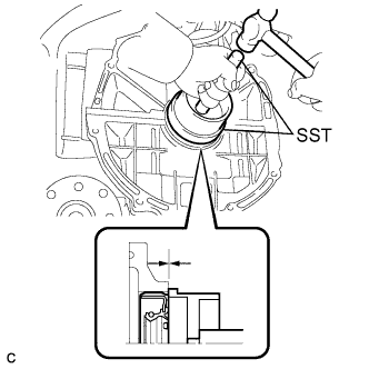
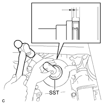
Using SST and a hammer, tap in the rear crankshaft oil seal until its surface is flush with the rear oil seal retainer edge.
- SST
- 09223-15030
- 09950-70010 ( 09951-07100 )
Note
-
Keep the lip free from foreign matter.
-
Do not tap on the oil seal at an angle.
-
-
INSTALL OIL CONTROL VALVE FILTER
-
Check that there is no foreign matter on the mesh part of the oil control valve filter.
-
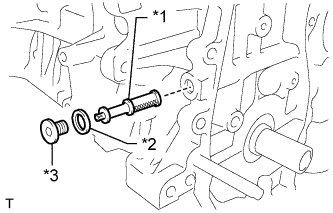
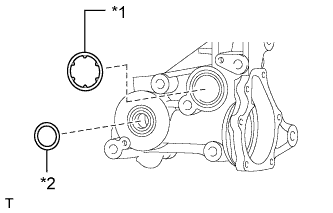
Text in Illustration *1 Oil Control Valve Filter *2 Gasket *3 Plug Using an 8 mm socket hexagon wrench, install a new gasket and the oil control valve filter with the plug.
- Torque:
- 30 N*m { 306 kgf*cm, 22 ft.*lbf }
-
-
INSTALL WATER INLET HOUSING (except TMC Made Engine)
-
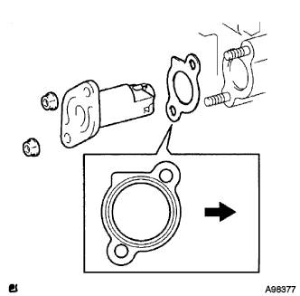
Text in Illustration *1 Water Inlet Housing O-ring *2 Water Inlet Housing Gasket Install a new water inlet housing O-ring and water inlet housing gasket to the water inlet housing.
-
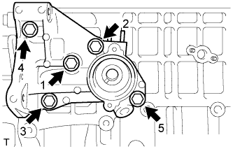
Install the water inlet housing to the cylinder block with the 5 bolts in the order shown in the illustration.
- Torque:
- 35 N*m { 357 kgf*cm, 26 ft.*lbf }
-
-
REPLACE STUD BOLT
Tech Tips
If a stud bolt is deformed or the threads are damaged, replace it.
-
Using an E5 "TORX" socket, remove the stud bolts.
-
Using an E5 "TORX" socket, install the stud bolts as shown the illustration.
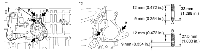
Text in Illustration *1 LH Side *2 Front Side - Torque:
- 5.0 N*m { 51 kgf*cm, 44 in.*lbf }
-
-
INSTALL CYLINDER BLOCK WATER DRAIN COCK SUB-ASSEMBLY (for TMC Made Engine without Engine Oil Cooler)
-
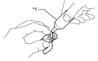
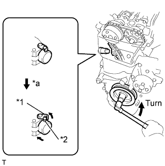
Text in Illustration *1 Adhesive Apply adhesive to 2 or 3 threads of the drain cock.
Adhesive Toyota Genuine Adhesive 1344, Three Bond 1344 or equivalent -
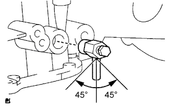
Install the water drain cock as shown in the illustration.
- Torque:
- 25 N*m { 255 kgf*cm, 18 ft.*lbf }
Note
-
Install the drain cock within 3 minutes.
-
Do not add coolant for 1 hour after installation.
-
Be sure to only tighten the drain cock up to 360 degrees to position the pipe. Do not loosen the drain cock to position the pipe.
-
Make sure to position the pipe within the range shown in the illustration.
-
Install the water drain cock plug to the water drain cock.
- Torque:
- 13 N*m { 130 kgf*cm, 9 ft.*lbf }
-
-
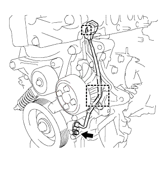
INSTALL WATER INLET HOUSING DRAIN COCK ASSEMBLY (except TMC Made Engine)
-
Text in Illustration *1 Adhesive Apply adhesive to 2 or 3 threads of the drain cock.
Adhesive Toyota Genuine Adhesive 1344, Three Bond 1344 or equivalent -
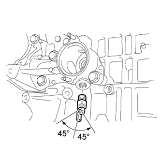
Install the water inlet housing drain cock within the range shown in the illustration.
- Torque:
- 25 N*m { 255 kgf*cm, 18 ft.*lbf }
Note
-
Install the drain cock within 3 minutes.
-
Do not add coolant for 1 hour after installation.
-
Be sure to only tighten the drain cock up to 360 degrees to position the pipe. Do not loosen the drain cock to position the pipe.
-
Make sure to position the pipe within the range shown in the illustration.
-
Install the water drain cock plug to the water drain cock.
- Torque:
- 13 N*m { 130 kgf*cm, 9 ft.*lbf }
-
-
INSTALL CYLINDER BLOCK WATER JACKET SPACER (for TMC Made Engine)
-
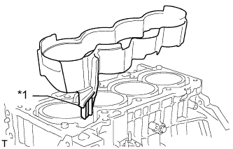
Text in Illustration *1 Slope Install the water jacket spacer as shown in the illustration.
Tech Tips
Be sure to face the slope to the front of the engine.
-
-
INSTALL CYLINDER BLOCK WATER JACKET SPACER (except TMC Made Engine)
-
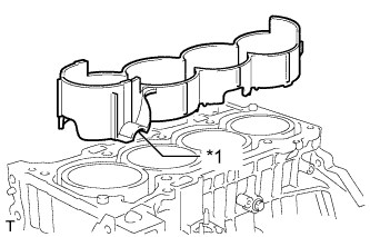
Text in Illustration *1 Slope Install the water jacket spacer as shown in the illustration.
Tech Tips
Be sure to face the slope to the front of the engine.
-
-
INSTALL CYLINDER HEAD GASKET
-
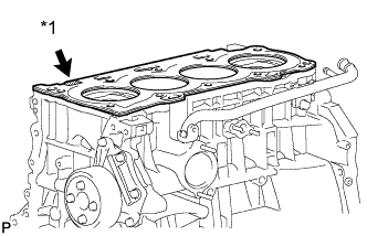
Text in Illustration *1 Lot No. Place a new cylinder head gasket on the cylinder block surface with the Lot No. stamp facing upward.
Note
-
Remove any oil from the contact surfaces.
-
Be careful of the installation direction.
-
-
-
INSTALL CYLINDER HEAD SUB-ASSEMBLY
-
Place the cylinder head on the cylinder head gasket.
Note
Place the cylinder head gently in order to avoid damaging the cylinder head gasket.
-
Install the cylinder head bolts.
Note
The cylinder head bolts are tightened in 2 successive steps.
-
Apply a light coat of engine oil to the threads and under the heads of the cylinder head set bolts.
-
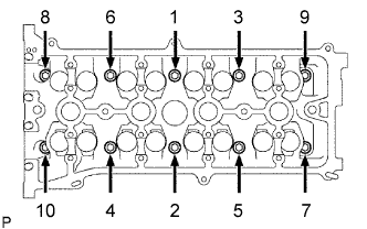
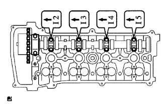
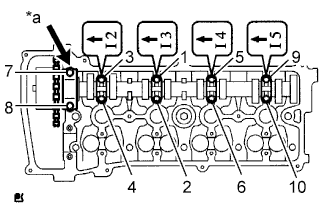
Using several steps, uniformly install and tighten the 10 cylinder head set bolts and plate washers with a 10 mm bi-hexagon wrench in the order shown in the illustration.
- Torque:
- 70 N*m { 714 kgf*cm, 52 ft.*lbf }
-
-
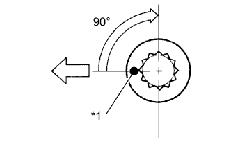
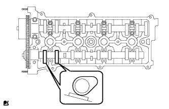
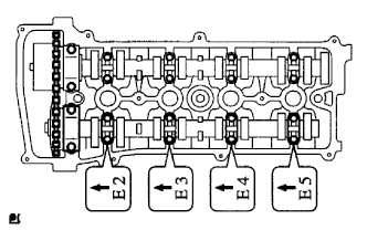
Text in Illustration *1 Paint Mark Engine Front Mark the front of the cylinder head bolts with paint.
-
Further tighten the cylinder head bolts 90° as shown in the illustration.
-
Check that the paint mark is now at a 90° angle to the front.
-
-
INSTALL CAMSHAFT TIMING OIL CONTROL VALVE ASSEMBLY
-
Apply a light coat of engine oil onto a new O-ring.
-
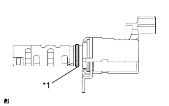
Text in Illustration *1 O-ring Install the O-ring to the camshaft timing oil control valve.
-
Install the camshaft timing oil control valve with the bolt.
- Torque:
- 9.0 N*m { 92 kgf*cm, 80 in.*lbf }
-
-
INSTALL CAMSHAFT TIMING GEAR ASSEMBLY
-
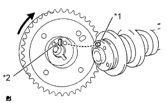
Text in Illustration *1 Straight Pin *2 Key Groove Put the camshaft timing gear and camshaft together with the straight pin and key groove misaligned, as shown in the illustration.
-
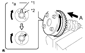
Text in Illustration *1 Straight Pin *2 Key Groove *a View A Turn the camshaft timing gear as shown in the illustration while pushing it gently against the camshaft. Push further at the position where the pin fits into the groove.
Note
Be sure not to turn the camshaft timing gear to the retard direction (clockwise).
-
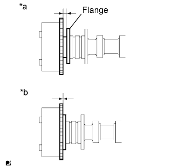
Text in Illustration *a Incorrect *b Correct Check that there is no clearance between the timing gear and camshaft flange.
-
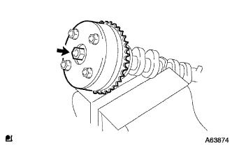
Tighten the flange bolt with the camshaft timing gear assembly fixed in place.
- Torque:
- 54 N*m { 551 kgf*cm, 40 ft.*lbf }
-
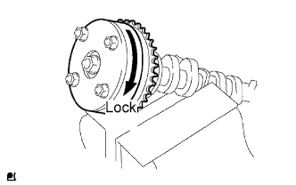
Check that the camshaft timing gear assembly can move to the retard direction (clockwise) and is locked in the most retarded position.
-
-
INSTALL NO. 2 CAMSHAFT TIMING SPROCKET
-
Clamp the camshaft in a vise, then install the camshaft timing sprocket with the bolt.
- Torque:
- 54 N*m { 551 kgf*cm, 40 ft.*lbf }
-
-
INSTALL NO. 1 CAMSHAFT BEARING
-
Clean the installation surfaces of the cap and the inner and outer surfaces of the bearing.
Note
Keep the installation surfaces and the back surfaces of the bearing free of engine oil.
-
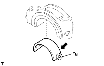
Text in Illustration *a Claw Align the claws and install the No. 1 camshaft bearing onto the No. 1 camshaft bearing cap.
-
-
INSTALL NO. 2 CAMSHAFT BEARING
-
Clean the installation surfaces of the cap and the inner and outer surfaces of the bearing.
Note
Keep the installation surfaces and the back surfaces of the bearing free of engine oil.
-
Install the No. 2 camshaft bearing onto the cylinder head.
-
-
INSTALL CAMSHAFT
-
Apply a light coat of engine oil to the journal portion.
-
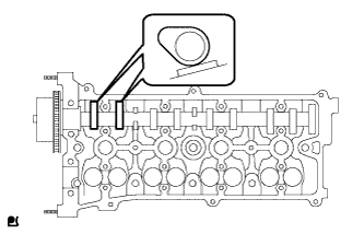
Place the camshaft on the cylinder head with the No. 1 cam lobes facing the directions shown in the illustration.
-
Apply a light coat of engine oil to the threads and under the heads of the bearing cap bolts.
-
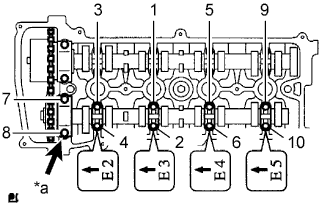
Examine the front marks and numbers, and check that the order is as shown in the illustration. Then install the bearing caps into the cylinder head.
-
Text in Illustration *a No. 1 Using several steps, uniformly tighten the 10 bearing cap bolts in the sequence shown in the illustration.
- Torque:
- No. 1 Bearing cap
- 30 N*m { 301 kgf*cm, 22 ft.*lbf }
- No. 3 Bearing cap
- 9.0 N*m { 92 kgf*cm, 80 in.*lbf }
-
-
INSTALL NO. 2 CAMSHAFT
-
Apply a light coat of engine oil to the journal portion of the No. 2 camshaft.
-
Place the camshaft on the cylinder head with the No. 2 cam lobes facing the directions shown in the illustration.
-
Apply a light coat of engine oil to the threads and under the heads of the bearing cap bolts.
-
Examine the front marks and numbers, and check that the order is as shown in the illustration. Then install the bearing caps onto the cylinder head.
-
Text in Illustration *a No. 2 Using several steps, uniformly tighten the 10 bearing cap bolts in the sequence shown in the illustration.
- Torque:
- No. 2 Bearing cap
- 30 N*m { 301 kgf*cm, 22 ft.*lbf }
- No. 3 Bearing cap
- 9.0 N*m { 92 kgf*cm, 80 in.*lbf }
-
-
INSTALL KEYS
-
Install the 2 keys.
-
-
INSTALL NO. 2 CHAIN SUB-ASSEMBLY
-
Set the crankshaft key into the left horizontal position.
-
Turn the oil pump drive shaft so that the cutout faces upward.
-
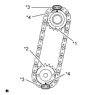
Text in Illustration *1 Oil Pump Drive Gear *2 Oil Pump Drive Shaft Gear *3 Mark Link *4 Timing Mark Align the yellow mark links with the timing marks of each gear as shown in the illustration.
-
Install the sprockets onto the crankshaft and oil pump shaft with the chain on the gears.
-
Temporarily tighten the oil pump drive shaft gear with the nut.
-
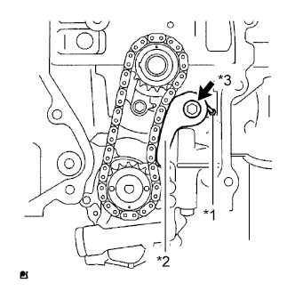
Text in Illustration *1 Spring *2 Chain Tensioner Plate *3 Bolt Insert the damper spring into the adjusting hole, and then install the chain tensioner plate with the bolt.
- Torque:
- 12 N*m { 122 kgf*cm, 9 ft.*lbf }
-
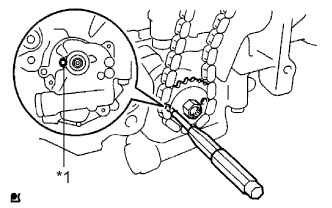
Text in Illustration *1 Groove Align the adjusting hole of the oil pump drive shaft gear with the groove of the oil pump.
-
Insert a 4 mm diameter bar into the adjusting hole of the oil pump drive shaft gear to lock the gear in position, and then tighten the nut.
- Torque:
- 30 N*m { 306 kgf*cm, 22 ft.*lbf }
-
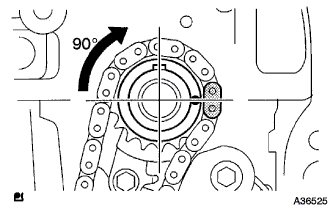
Rotate the crankshaft 90° clockwise, and position the crankshaft key to face up as shown in the illustration.
-
-
INSTALL CRANKSHAFT TIMING SPROCKET
-
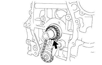
Install the crankshaft timing gear or sprocket to the crankshaft.
-
-
INSTALL NO. 1 CHAIN VIBRATION DAMPER
-
Install the No. 1 chain vibration damper with the 2 bolts.
- Torque:
- 9.0 N*m { 92 kgf*cm, 80 in.*lbf }
-
-
INSTALL CHAIN SUB-ASSEMBLY
-
Set the No. 1 cylinder to TDC/compression.
-

Text in Illustration *1 Timing Mark Turn the camshafts with a wrench (using the hexagonal lobe) to align the timing marks on the camshaft timing gear with the timing marks located on the No. 1 and No. 2 bearing caps as shown in the illustration.
-
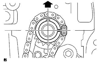
Using the crankshaft pulley bolt, turn the crankshaft to position the key on the crankshaft upward.
-
-
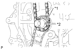
Text in Illustration *1 Timing Mark *2 Mark Link Install the chain onto the crankshaft timing sprocket with the gold or orange mark link aligned with the timing mark on the crankshaft.
-
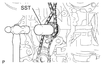
Using SST and a hammer, tap in the crankshaft timing sprocket.
- SST
- 09309-37010
-
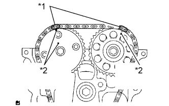
Text in Illustration *1 Mark Link *2 Timing Mark Align the gold or yellow links with the timing marks located on the camshaft timing gear and sprocket, then install the chain.
-
-
INSTALL CHAIN TENSIONER SLIPPER
-
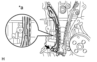
Text in Illustration *a Hold Install the chain tensioner slipper with the bolt.
- Torque:
- 19 N*m { 194 kgf*cm, 14 ft.*lbf }
-
-
INSTALL TIMING CHAIN GUIDE
-
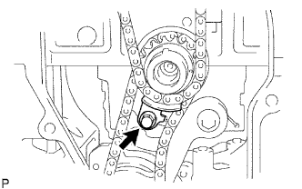
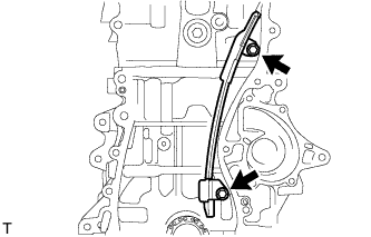
Install the timing chain guide with the bolt.
- Torque:
- 9.0 N*m { 92 kgf*cm, 80 in.*lbf }
-
-
INSTALL NO. 1 CRANKSHAFT POSITION SENSOR PLATE
-
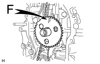
Install the sensor plate with the "F" mark facing forward.
-
-
INSTALL FRONT CRANKSHAFT OIL SEAL
-
Apply MP grease to the lip of a new front crankshaft oil seal.
-
Using SST and a hammer, tap in the front crankshaft oil seal until its surface is flush with the front oil seal retainer edge.
- SST
- 09223-22010
Note
-
Keep the lip free from foreign matter.
-
Do not tap on the oil seal at an angle.
-
-
INSTALL TIMING CHAIN COVER SUB-ASSEMBLY
-
Remove any old packing material and be careful not to drop any oil on the contact surfaces of the timing chain cover, cylinder head and cylinder block.
-
Apply seal packing (Diameter 4.0 to 4.5 mm (0.157 to 0.177 in.)) as shown in the illustration.
Text in Illustration 
Seal Packing Seal packing Toyota Genuine Seal Packing Black, Three Bond 1207B or equivalent Note
-
Remove any oil from the contact surfaces.
-
Install the chain cover within 3 minutes of applying seal packing.
-
Do not add engine oil for at least 2 hours after installing the chain cover.
-
-
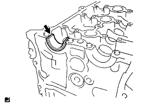
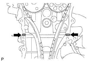
Apply a continuous bead of seal packing as shown in the illustration.
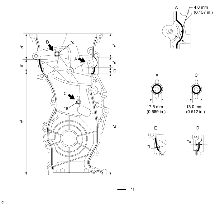
Text in Illustration *1 Seal Packing - - *a Seal Diameter: 2.5 to 3.0 mm (0.0984 to 0.118 in.) *b Seal Diameter: 3.0 mm (0.118 in.) *c Seal Diameter: 4.0 mm (0.157 in.) *d Seal Diameter: 4.0 to 4.5 mm (0.157 to 0.177 in.) *e Seal Diameter: 4.5 to 5.0 mm (0.177 to 0.197 in.) *f Seal Diameter: 5.5 to 6.0 mm (0.217 to 0.236 in.) Seal packing Toyota Genuine Seal Packing Black, Three Bond 1207B or equivalent Note
-
Remove any oil from the contact surfaces.
-
Install the chain cover within 3 minutes of applying seal packing.
-
Do not add engine oil for at least 2 hours after installing the chain cover.
-
-
Apply adhesive to the threads of the bolt A.
Seal packing Toyota Genuine Adhesive 1324, Three Bond 1324 or equivalent -
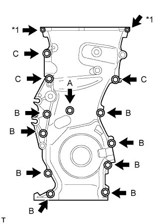
Text in Illustration *1 Nut Temporarily install the timing chain cover with the 12 bolts and 2 nuts.
Bolt Length Item Length Bolt A 30 mm (1.18 in.) length for 10 mm head Bolt B 30 mm (1.18 in.) length for 12 mm head Bolt C 40 mm (1.57 in.) length for 14 mm head -
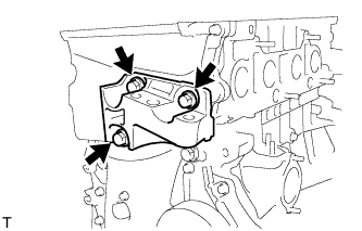
Temporarily install the engine mounting bracket RH with the 3 bolts.
-
Fully tighten the timing chain cover with the 15 bolts and 2 nuts as shown in the illustration.
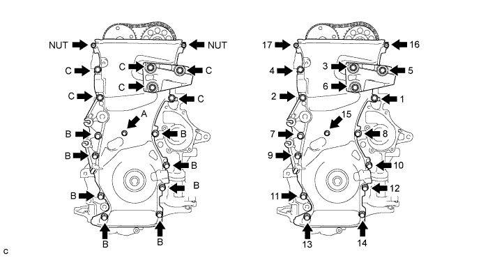
- Torque:
- Bolt A
- 9.0 N*m { 92 kgf*cm, 80 in.*lbf }
- Bolt B
- 25 N*m { 255 kgf*cm, 18 ft.*lbf }
- Bolt C
- 55 N*m { 561 kgf*cm, 41 ft.*lbf }
- Nut
- 11 N*m { 112 kgf*cm, 8 ft.*lbf }
-
Using an E10 "TORX" socket, install the stud bolt for the V-ribbed belt tensioner.
- Torque:
- 22 N*m { 220 kgf*cm, 16 ft.*lbf }
-
-
INSTALL NO. 1 CHAIN TENSIONER ASSEMBLY
-
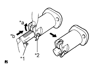
Text in Illustration *1 Pin *2 Hook *a Raise *b Push Release the ratchet pawl, then fully push in the plunger and set the hook to the pin so that the plunger is in the position shown in the illustration.
-
Install a new gasket and the chain tensioner with the 2 nuts.
Text in Illustration Engine Front - Torque:
- 9.0 N*m { 92 kgf*cm, 80 in.*lbf }
Note
When installing the chain tensioner, set the hook again if the hook releases the plunger.
-
-
INSTALL V-RIBBED BELT TENSIONER ASSEMBLY
-
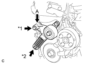
Text in Illustration *1 Bolt *2 Nut Temporarily install the V-ribbed belt tensioner assembly with the nut.
Note
Do not lift the engine more than necessary.
-
Slightly push down on the V-ribbed belt tensioner assembly at part (A) to align the holes of the engine and tensioner as shown in the illustration, and temporarily install the bolt.
-
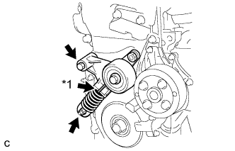
Text in Illustration *1 Pin Tighten the bolt and nut to install the V-ribbed belt tensioner.
- Torque:
- 60 N*m { 612 kgf*cm, 44 ft.*lbf }
Note
-
When replacing the V-ribbed belt tensioner with a new one, do not pull out the pin.
-
The pin will be removed in a later step.
-
-
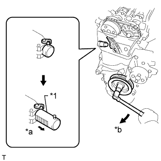
INSTALL CRANK POSITION SENSOR (for TMC Made Engine)
-

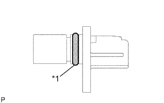
Text in Illustration *1 New O-ring Apply a light coat of engine oil to the O-ring on the crank position sensor.
-
Install the crank position sensor with the bolt.
- Torque:
- 9.0 N*m { 92 kgf*cm, 80 in.*lbf }
Note
Do not twist the O-ring.
-
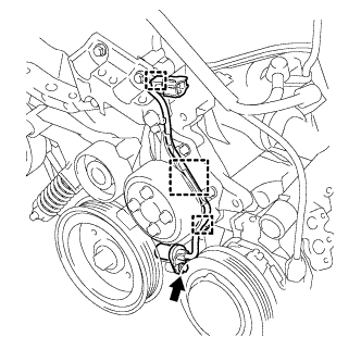
Install the 2 wire harness clamps.
-
Install the connector to the connector bracket.
-
-
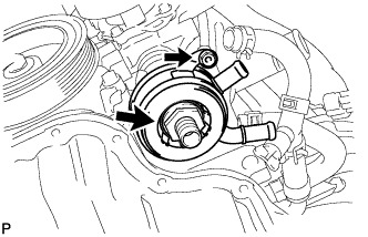
INSTALL CRANK POSITION SENSOR (except TMC Made Engine)
-
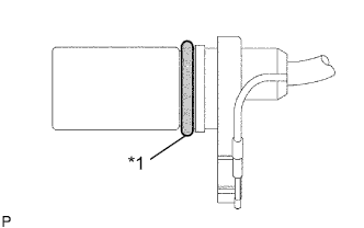
Text in Illustration *1 New O-ring Apply a light coat of engine oil to the O-ring on the crank position sensor.
-
Install the crank position sensor with the bolt.
- Torque:
- 9.0 N*m { 92 kgf*cm, 80 in.*lbf }
Note
Do not twist the O-ring.
-
Install the wire harness clamp.
-
Install the connector to the connector bracket.
-
-
INSTALL OIL PAN SUB-ASSEMBLY
-
Remove any old packing material and be careful not to drop any oil on the contact surfaces of the cylinder block and oil pan.
-
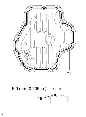
Text in Illustration *1 Seal Packing *a Seal Diameter: 3.0 to 4.0 mm Apply a continuous bead of seal packing (diameter 3.0 to 4.0 mm (0.118 to 0.157 in.)) as shown in the illustration.
Seal packing Toyota Genuine Seal Packing Black, Three Bond 1207B or equivalent Note
-
Remove any oil from the contact surfaces.
-
Install the oil pan within 3 minutes of applying seal packing.
-
Do not add engine oil for at least 2 hours after installing the oil pan.
-
-
Install the oil pan onto the cylinder block.
-
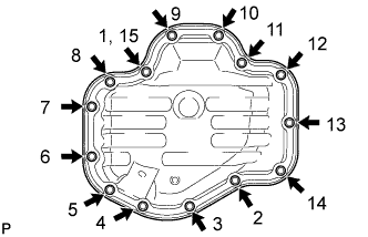
Uniformly tighten the 12 bolts and 2 nuts in the sequence shown in the illustration.
- Torque:
- 9.0 N*m { 92 kgf*cm, 80 in.*lbf }
-
-
INSTALL OIL PAN DRAIN PLUG
-
Install the oil pan drain plug with a new gasket.
- Torque:
- 40 N*m { 408 kgf*cm, 30 ft.*lbf }
-
-
INSTALL WATER PUMP ASSEMBLY (for TMC Made Engine)
-
Remove any old seal packing material from the contact surfaces.
-
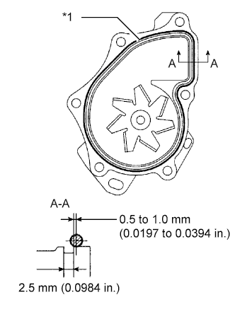
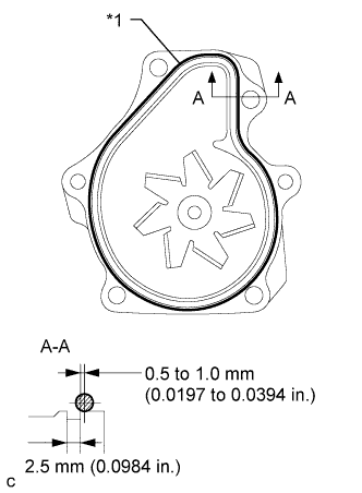
Text in Illustration *1 Seal Packing Apply a continuous line of seal packing as shown in the illustration.
Seal packing Toyota Genuine Seal Packing 1282B, Three Bond 1282B or equivalent Standard seal diameter 2.2 to 2.5 mm (0.0866 to 0.0984 in.) Note
-
Remove any oil from the contact surfaces.
-
The parts must be set within 3 minutes after applying seal packing. Otherwise, the material must be removed and reapplied.
-
-
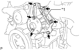
Text in Illustration *1 Clamp Bracket Install the water pump assembly and clamp bracket with the 4 bolts and 2 nuts.
- Torque:
- 9.0 N*m { 92 kgf*cm, 80 in.*lbf }
-
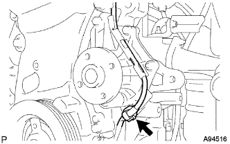
Install the wire of the crankshaft position sensor onto the clamp bracket.
-
Install the clamp of the crankshaft position sensor onto the water pump.
-
-
INSTALL WATER PUMP ASSEMBLY (except TMC Made Engine)
-
Remove any old seal packing material from the contact surfaces.
-
Text in Illustration *1 Seal Packing Apply a continuous line of seal packing as shown in the illustration.
Seal packing Toyota Genuine Seal Packing 1282B, Three Bond 1282B or equivalent Standard seal diameter 2.2 to 2.5 mm (0.0866 to 0.0984 in.) Note
-
Remove any oil from the contact surfaces.
-
The parts must be set within 3 minutes after applying seal packing. Otherwise, the material must be removed and reapplied.
-
-
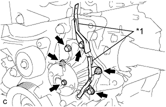
Text in Illustration *1 Clamp Bracket Install the water pump assembly and 2 clamp brackets with the 4 bolts and 2 nuts.
- Torque:
- 9.0 N*m { 92 kgf*cm, 80 in.*lbf }
-
Install the wire of the crankshaft position sensor onto the clamp bracket.
-
Connect the connector of the crankshaft position sensor.
-
-
INSTALL WATER PUMP PULLEY
-
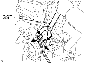
Using SST, install the water pump pulley with the 4 bolts.
- SST
- 09960-10010 ( 09962-01000, 09963-00700 )
- Torque:
- 26 N*m { 265 kgf*cm, 19 ft.*lbf }
-
-
INSTALL CRANKSHAFT PULLEY
-
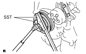
Using SST, secure the pulley in place and tighten the bolt.
- SST
- 09213-54015 ( 91651-60855 )
- 09330-00021
- Torque:
- 180 N*m { 1835 kgf*cm, 133 ft.*lbf }
-
Text in Illustration *1 Hook *2 Pin *a Disconnect Turn the crankshaft counterclockwise, then disconnect the hook from the pin.
-
Text in Illustration *1 Plunger *a Extend *b Turn Turn the crankshaft clockwise, then check that the plunger is extended.
-
-
INSPECT VALVE CLEARANCE
-
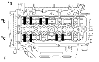
Text in Illustration *a No. 1 Cylinder TDC/Compression *b Intake *c Exhaust Check only the valves indicated in the illustration.
-
Using a feeler gauge, measure the clearance between the valve lifter and camshaft.
Standard Valve Clearance (Cold) Item Specified Condition Intake 0.19 to 0.29 mm (0.00748 to 0.0114 in.) Exhaust 0.38 to 0.48 mm (0.0150 to 0.0189 in.) -
Record any out-of-specification valve clearance measurements. They will be used later to determine the required replacement valve clearance lifters.
-
-
Turn the crankshaft 1 revolution (360°) and set the No. 4 cylinder to TDC/Compression.
-
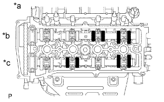
Text in Illustration *a No. 4 Cylinder TDC/Compression *b Intake *c Exhaust Check only the valves indicated in the illustration.
-
Using a feeler gauge, measure the clearance between the valve lifter and camshaft.
Standard Valve Clearance (Cold) Item Specified Condition Intake 0.19 to 0.29 mm (0.00748 to 0.0114 in.) Exhaust 0.38 to 0.48 mm (0.0150 to 0.0189 in.) -
Record any out-of-specification valve clearance measurements. They will be used later to determine the required replacement valve lifters.
-
-
-
ADJUST VALVE CLEARANCE
-
Set No. 1 cylinder to TDC/compression Click here.
-
Remove the No. 1 chain tensioner Click here.
-
Loosen the camshaft timing sprocket Click here.
-
Remove the No. 2 camshaft Click here.
-
Remove the camshaft Click here.
-
Remove the valve lifters.
-
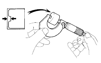
Using a micrometer, measure the thickness of the removed valve lifters.
-
Calculate the thickness of a new lifter so that the valve clearance comes within the specified values.
New Lifter Thickness Item Specification Intake A = B + (C - 0.24 mm (0.00945 in.)) Exhaust A = B + (C - 0.43 mm (0.0169 in.)) A New lifter thickness B Used lifter thickness C Measured valve clearance CALCULATION EXAMPLE (Intake):
-
Measured intake valve clearance = 0.40 mm (0.0157 in.)
(Measured - Specification = Excess clearance)
-
0.40 mm (0.0157 in.) - 0.24 mm (0.00945 in.) = 0.16 mm (0.00630 in.)
-
Measured used lifter thickness = 5.250 mm (0.2067 in.)
-
New lifter thickness = 5.410 mm (0.2130 in.)
(Excess clearance + Used lifter thickness = Ideal new lifter)
-
0.16 mm (0.00630 in.) + 5.250 mm (0.2067 in.) = 5.410 mm (0.2130 in.)
-
Closest new lifter = 5.420 mm (0.2134 in.)
-
Select No. 42 lifter
-
-
Select a new lifter with a thickness as close as possible to the calculated values.
Tech Tips
-
Lifters are available in 35 sizes in increments of 0.020 mm (0.000787 in.), from 5.060 to 5.740 mm (0.1992 to 0.2260 in.).
-
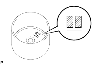
The identification number inside the valve lifters shows the value to 2 decimal places. (The illustration shows 5.420 mm (0.2134 in.)
-
-
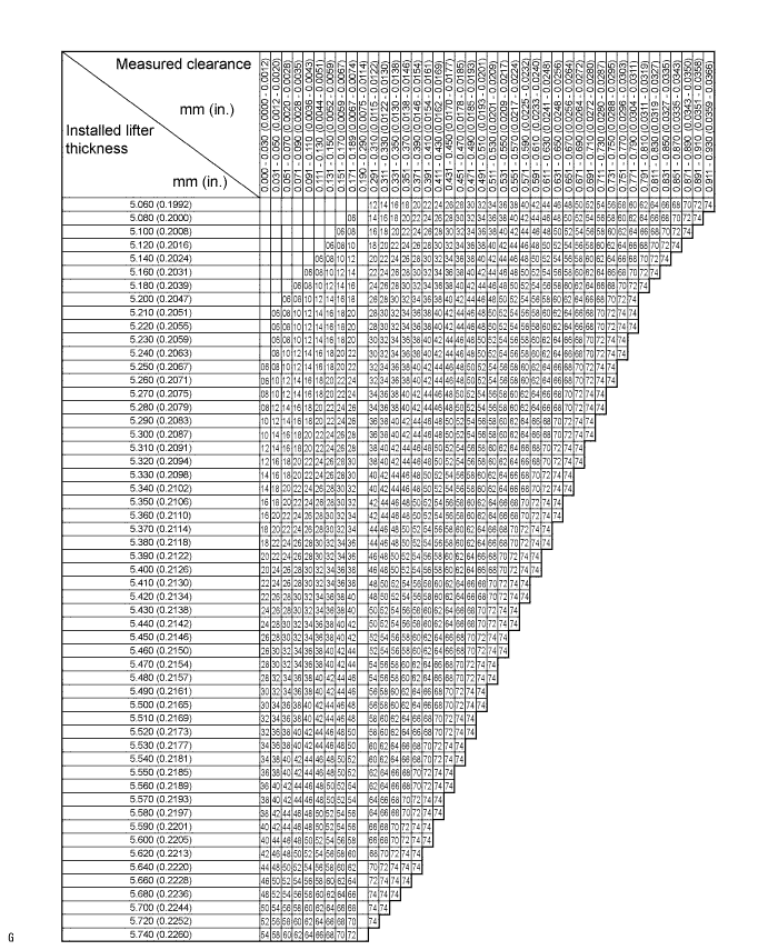
Valve lifter selection chart (intake).
New Lifter Thickness Lifter No. Thickness
mm (in.)
Lifter No. Thickness
mm (in.)
Lifter No. Thickness
mm (in.)
06 5.060 (0.1992) 30 5.300 (0.2087) 54 5.540 (0.2181) 08 5.080 (0.2000) 32 5.320 (0.2094) 56 5.560 (0.2189) 10 5.100 (0.2008) 34 5.340 (0.2102) 58 5.580 (0.2197) 12 5.120 (0.2016) 36 5.360 (0.2110) 60 5.600 (0.2205) 14 5.140 (0.2024) 38 5.380 (0.2118) 62 5.620 (0.2213) 16 5.160 (0.2031) 40 5.400 (0.2126) 64 5.640 (0.2220) 18 5.180 (0.2039) 42 5.420 (0.2134) 66 5.660 (0.2228) 20 5.200 (0.2047) 44 5.440 (0.2142) 68 5.680 (0.2236) 22 5.220 (0.2055) 46 5.460 (0.2150) 70 5.700 (0.2244) 24 5.240 (0.2063) 48 5.480 (0.2157) 72 5.720 (0.2252) 26 5.260 (0.2071) 50 5.500 (0.2165) 74 5.740 (0.2260) 28 5.280 (0.2079) 52 5.520 (0.2173) - - Standard intake valve clearance (cold) 0.19 to 0.29 mm (0.00748 to 0.0114 in.) EXAMPLE:
The 5.250 mm (0.2067 in.) lifter is installed, and the measured clearance is 0.400 mm (0.0157 in.). Replace the 5.250 mm (0.2067 in.) lifter with a new No. 42 lifter.
-
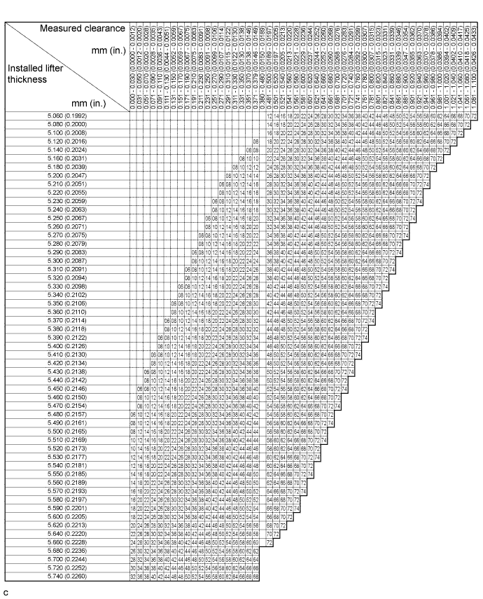
Valve lifter selection chart (exhaust).
New Lifter Thickness Lifter No. Thickness
mm (in.)
Lifter No. Thickness
mm (in.)
Lifter No. Thickness
mm (in.)
06 5.060 (0.1992) 30 5.300 (0.2087) 54 5.540 (0.2181) 08 5.080 (0.2000) 32 5.320 (0.2094) 56 5.560 (0.2189) 10 5.100 (0.2008) 34 5.340 (0.2102) 58 5.580 (0.2197) 12 5.120 (0.2016) 36 5.360 (0.2110) 60 5.600 (0.2205) 14 5.140 (0.2024) 38 5.380 (0.2118) 62 5.620 (0.2213) 16 5.160 (0.2031) 40 5.400 (0.2126) 64 5.640 (0.2220) 18 5.180 (0.2039) 42 5.420 (0.2134) 66 5.660 (0.2228) 20 5.200 (0.2047) 44 5.440 (0.2142) 68 5.680 (0.2236) 22 5.220 (0.2055) 46 5.460 (0.2150) 70 5.700 (0.2244) 24 5.240 (0.2063) 48 5.480 (0.2157) 72 5.720 (0.2252) 26 5.260 (0.2071) 50 5.500 (0.2165) 74 5.740 (0.2260) 28 5.280 (0.2079) 52 5.520 (0.2173) - - Standard exhaust valve clearance (cold) 0.38 to 0.48 mm (0.0150 to 0.0189 in.) EXAMPLE:
The 5.340 mm (0.2102 in.) lifter is installed, and the measured clearance is 0.510 mm (0.0201 in.). Replace the 5.340 mm (0.2102 in.) lifter with a new No. 42 lifter.
-
Install the selected valve lifter.
-
Install the camshaft Click here.
-
Install the No. 2 camshaft Click here.
-
Install the No. 1 chain tensioner Click here.
-
-
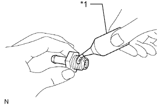
INSTALL CAMSHAFT POSITION SENSOR
-
Text in Illustration *1 O-ring Apply a light coat of engine oil onto the O-ring of the sensor.
-
Install the camshaft position sensor with the bolt.
- Torque:
- 9.0 N*m { 92 kgf*cm, 80 in.*lbf }
-
-
INSTALL CYLINDER HEAD COVER GASKET
-
Install the cylinder head cover gasket onto the cylinder head cover.
-
-
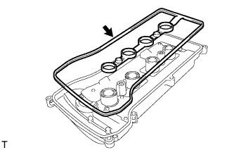
INSTALL CYLINDER HEAD COVER SUB-ASSEMBLY
-
Remove any old packing material from the contact surfaces.
-
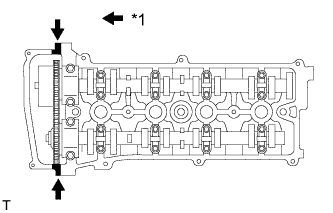
Text in Illustration *1 Seal Packing Apply seal packing to the 2 locations shown in the illustration.
Seal Packing Toyota Genuine Seal Packing Black, Three Bond 1207B or equivalent Note
-
Remove any oil from the contact surfaces.
-
Install the cylinder head cover within 3 minutes of applying seal packing.
-
Do not start the engine for at least 2 hours after installing the cylinder head cover.
-
-
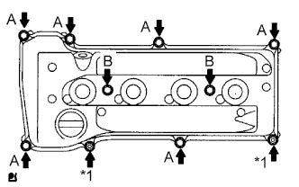
Text in Illustration *1 Nut Install the cylinder head cover with the 8 bolts and 2 nuts.
- Torque:
- Bolt A
- 11 N*m { 112 kgf*cm, 8 ft.*lbf }
- Bolt B
- 14 N*m { 143 kgf*cm, 10 ft.*lbf }
- Nut
- 11 N*m { 112 kgf*cm, 8 ft.*lbf }
-
-
INSTALL OIL FILTER UNION (except TMC Made Engine with Engine Oil Cooler)
-
Using a 12 mm socket hexagon wrench, install the oil filter union.
- Torque:
- 30 N*m { 306 kgf*cm, 22 ft.*lbf }
-
-
INSTALL ENGINE OIL COOLER (for TMC Made Engine with Engine Oil Cooler)
-
Clean the oil cooler contact surface on the cooler mounting.
-
Install a new O-ring to the oil cooler.
-
Apply a light coat of engine oil on the threads and under the head of the oil cooler union.
-
Install the oil cooler with the plate washer, oil cooler union and nut.
- Torque:
- Oil cooler union
- 79 N*m { 806 kgf*cm, 58 ft.*lbf }
- Nut
- 9.0 N*m { 92 kgf*cm, 80 in.*lbf }
-
-
INSTALL OIL FILTER SUB-ASSEMBLY
-
Check and clean the oil filter sub-assembly installation surface.
-
Apply clean engine oil to the gasket of a new oil filter sub-assembly.
-
Lightly screw the oil filter sub-assembly into place by hand. Tighten it until the gasket contacts the seat.
-
Using SST, tighten the oil filter sub-assembly.
- SST
- 09228-06501
-
Depending on the work space available, choose from the following:
-
If enough space is available, use a torque wrench to tighten the oil filter sub-assembly.
- Torque:
- 18 N*m { 184 kgf*cm, 13 ft.*lbf }
-
If enough space is not available to use a torque wrench, tighten the oil filter sub-assembly a 3/4 turn by hand or use a common wrench.
-
-
-
INSTALL SPARK PLUG
-
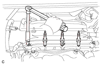
Install the 4 spark plugs.
- Torque:
- 19 N*m { 194 kgf*cm, 14 ft.*lbf }
-
-
INSTALL VENTILATION VALVE SUB-ASSEMBLY
-
Text in Illustration *1 Adhesive Apply adhesive to the threads of the ventilation valve.
Adhesive Toyota Genuine Adhesive 1324, Three Bond 1324 or equivalent -
Using a 22 mm deep socket wrench, install the ventilation valve onto the cylinder head cover.
- Torque:
- 19 N*m { 194 kgf*cm, 14 ft.*lbf }
-
-
INSTALL OIL FILLER CAP GASKET
-
Install the oil filler cap gasket onto the oil filler cap.
-
-
INSTALL OIL FILLER CAP SUB-ASSEMBLY
-
Install the oil filler cap onto the cylinder head cover.
-