HEATED OXYGEN SENSOR REMOVAL

-
REMOVE COWL SIDE TRIM BOARD RH (for RHD)
-

Remove the clip.
-
Disengage the clip, claw and 2 guides, and remove the cowl side trim board RH.
-
-
REMOVE COWL SIDE TRIM BOARD LH (for LHD)
-
Remove the clip(A).
-
Disengage the clip, claw and 2 guides, and remove the cowl side trim board LH.
-
-
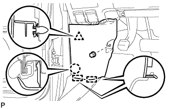
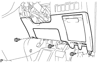
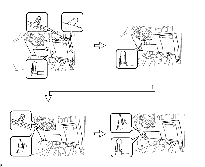
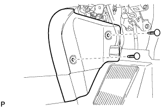
REMOVE NO. 1 INSTRUMENT PANEL UNDER COVER SUB-ASSEMBLY (for RHD)
-

Remove the 2 screws <B>.
-
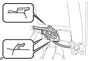
Disengage the 2 claws and 2 guides.
-
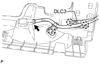
Disengage the 2 claws and disconnect the DLC3.
-
Disengage the clamp.
-
Disconnect each connector and remove the No. 1 instrument panel under cover sub-assembly.
-
-
REMOVE NO. 1 INSTRUMENT PANEL UNDER COVER SUB-ASSEMBLY (for LHD)
-

Remove the 2 screws <B>.
-
Disengage the 2 claws and guide.
-
Disengage the clamp.
-
Disconnect each connector and remove the No. 1 instrument panel under cover sub-assembly.
-
-
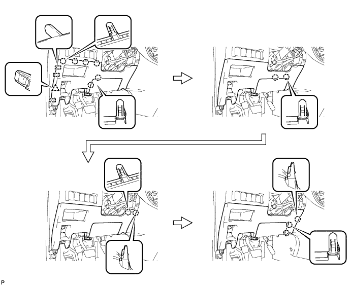
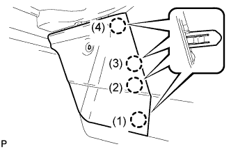
REMOVE LOWER INSTRUMENT PANEL FINISH PANEL (for RHD)
-
Disengage the 3 claws and disconnect the hood lock control cable assembly.
-

Disengage the 3 claws and disconnect the fuel lid lock control cable assembly.
-
Remove the 3 screws <B>.
-
Disengage the 14 claws and the 3 guides, and remove the lower instrument panel finish panel as shown in the illustration.
Note
-
Make sure to follow the order shown in the illustration to avoid damage to the lower instrument panel finish panel.
-
While supporting the knee airbag, remove the lower instrument panel finish panel.
-
-
-
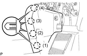
REMOVE LOWER INSTRUMENT PANEL FINISH PANEL (for LHD)
-

Disengage the 3 claws and disconnect the hood lock control cable assembly.
-
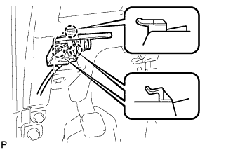
Disengage the 3 claws and disconnect the fuel lid lock control cable assembly.
-

Disconnect the fuel filler opening lid lock sub-assembly and remove the fuel lid lock open lever sub-assembly.
-
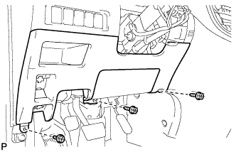
Remove the 3 screws <B>.
-
Disengage the 13 claws, clip and the 3 guides and remove the lower instrument panel finish panel as shown in the illustration.
Note
-
Make sure to follow the order shown in the illustration to avoid damage to the lower instrument panel finish panel.
-
While supporting the knee airbag, remove the lower instrument panel finish panel.
-
-
-
REMOVE CENTER FLOOR CARPET COVER LH
-

Using a clip remover, remove the clip.
-
Disengage the 4 claws and remove the center floor carpet cover LH in the order shown in the illustration.
Tech Tips
Remove the center floor carpet cover LH while pushing on the instrument cluster finish panel.
-
-
REMOVE CENTER FLOOR CARPET COVER RH (for RHD)
-
Using a clip remover, remove the 2 clips.
-
Disengage the 4 claws and remove the center floor carpet cover RH in the order shown in the illustration.
Tech Tips
Remove the center floor carpet cover RH while pushing on the instrument cluster finish panel.
-
-
REMOVE CENTER FLOOR CARPET COVER RH (for LHD)
-
Using a clip remover, remove the clip.
-
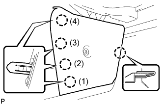
Disengage the 5 claws and remove the center floor carpet cover RH in the order shown in the illustration.
Tech Tips
Remove the center floor carpet cover RH while pushing on the instrument cluster finish panel.
-
-
REMOVE GLOVE COMPARTMENT DOOR ASSEMBLY
-
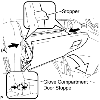
Disengage the claw and release the glove compartment door stopper.
-
Slightly bend stoppers (A) and (B) in the directions indicated by the arrows in the illustration and pull the glove compartment door assembly until the stoppers are released.
-
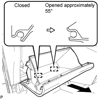
Open the glove compartment door assembly to approximately 55° from its closed position. Pull it horizontally toward the rear of the vehicle to disengage the 2 hinges and remove the glove compartment door assembly.
Note
Pulling the glove compartment door assembly upward to remove it causes the hinges to deform. Be sure to pull out the glove compartment door assembly horizontally.
-
-
REMOVE INSTRUMENT PANEL BOX ASSEMBLY
-
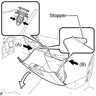
Slightly bend stoppers (A) and (B) in the directions indicated by the arrows in the illustration and pull the instrument panel box assembly until the stoppers are released.
-
Remove the damper clip.
-
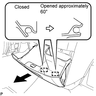
Open the instrument panel box assembly to approximately 60° from its closed position. Pull it horizontally toward the rear of the vehicle to disengage the 2 hinges and remove the instrument panel box assembly.
Note
Pulling the instrument panel box assembly upward to remove it causes the hinges to deform. Be sure to pull out the instrument panel box horizontally.
-
-
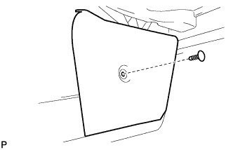
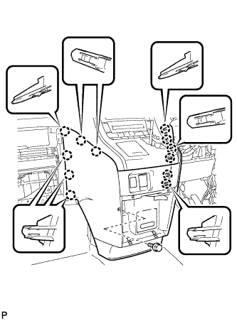
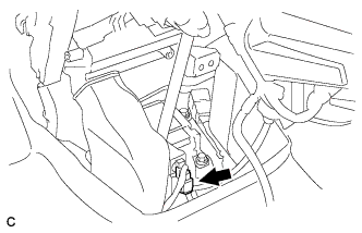
REMOVE INSTRUMENT CLUSTER FINISH PANEL ASSEMBLY
-
Remove the bolt <C>.
-
Disengage the 12 claws.
Tech Tips
First disengage the 6 claws for the right side and then pull the panel to the rear of the vehicle to disengage the 6 claws for the left side.
-
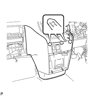
Disengage the 3 claws.
-
Disconnect each connector and remove the instrument cluster finish panel assembly.
-
-
REMOVE OXYGEN SENSOR (for Bank 1 Sensor 2)
-
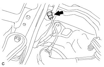
Disconnect the oxygen sensor connector.
-
Remove the grommet.
-
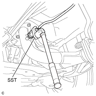
Using SST, remove the oxygen sensor from the center exhaust pipe assembly.
- SST
- 09224-00010
-
-
REMOVE NO. 1 ENGINE UNDER COVER
-
REMOVE CENTER EXHAUST PIPE ASSEMBLY (for Front Side)
-
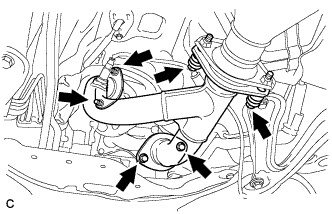
Remove the 4 bolts, 2 nuts, 2 compression springs and center exhaust pipe assembly (for Front Side).
-
Remove the 3 gaskets from the center exhaust pipe assembly (for Front Side).
-
-
REMOVE FRONT EXHAUST PIPE ASSEMBLY
-
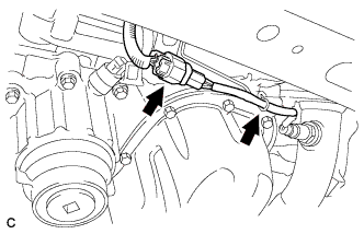
Disconnect the No. 2 oxygen sensor connector (for Bank 2).
-
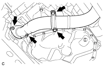
Remove the 2 bolts and No. 1 exhaust pipe support bracket.
-
Remove the 2 nuts and front exhaust pipe assembly.
-
Remove the gasket from the front exhaust pipe assembly.
-
-
REMOVE NO. 2 OXYGEN SENSOR (for Bank 2 Sensor 2)
-
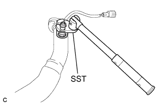
Using SST, remove the No. 2 oxygen sensor from the front exhaust pipe assembly.
- SST
- 09224-00010
-