IGNITION COIL AND SPARK PLUG REMOVAL

-
REMOVE NO. 1 ENGINE UNDER COVER
-
DRAIN ENGINE COOLANT
CAUTION:
Do not remove the reserve tank cap, cylinder block drain cock plugs or radiator drain cock plug while the engine and radiator assembly are still hot. Pressurized, hot engine coolant and steam may be released and cause serious burns.
-
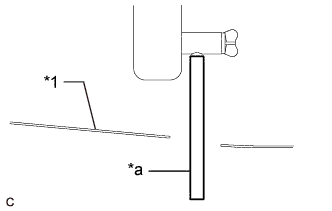
Text in Illustration *1 No. 1 Engine Under Cover *a Hose Connect a hose with an inside diameter of 9 mm (0.354 in.) to the radiator drain cock as shown in the illustration.
-
Loosen the radiator drain cock plug.
-
Remove the reserve tank cap. Then drain the engine coolant.
-
Loosen the cylinder block drain cock plug (for Bank 1).
-
Loosen the cylinder block drain cock plug (for Bank 2, w/ Cylinder Block Drain Cock Plug).
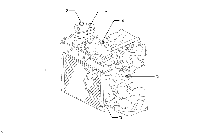
Text in Illustration *1 Radiator Reserve Tank *2 Reserve Tank Cap *3 Radiator Drain Cock Plug *4 Air Drain Cock Plug *5 Cylinder Block Drain Cock Plug (for Bank 1) *6 Cylinder Block Drain Cock Plug (for Bank 2, w/ Cylinder Block Drain Cock Plug) Tech Tips
Collect the engine coolant in a container and dispose of it according to the regulations in your area.
-
Disconnect a hose with an inside diameter of 9 mm (0.354 in.) from the radiator drain cock.
-
-
REMOVE WINDSHIELD WIPER MOTOR AND LINK ASSEMBLY
-
Remove the windshield wiper motor and link assembly Click here.
-
-
SEPARATE BRAKE MASTER CYLINDER RESERVOIR ASSEMBLY
-
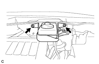
Remove the 2 nuts and separate the brake master cylinder reservoir with bracket from the outer cowl top panel.
-
-
REMOVE COWL TOP PANEL OUTER SUB-ASSEMBLY
-
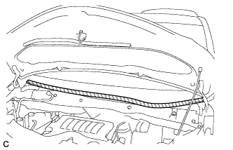
Apply protective tape as shown in the illustration.
Text in Illustration 
Protective Tape -
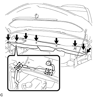
Disconnect the 2 clamps from the outer cowl top panel.
-
Remove the 8 bolts.
-
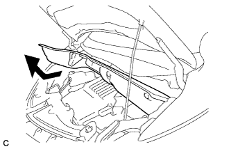
Remove the outer cowl top panel as shown in the illustration.
-
-
REMOVE RADIATOR COVER SUB-ASSEMBLY (for ALPHARD)
-
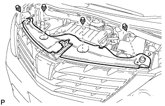
Using a clip remover, remove the 4 clips and radiator cover sub-assembly.
-
-
REMOVE RADIATOR COVER SUB-ASSEMBLY (for VELLFIRE)
-
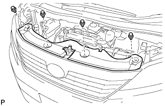
Using a clip remover, remove the 4 clips and radiator cover sub-assembly.
-
-
REMOVE V-BANK COVER SUB-ASSEMBLY
-
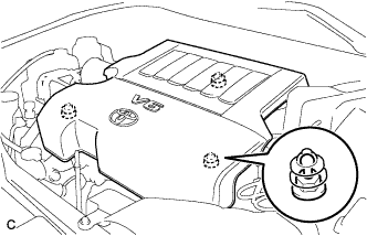
Hold the front of the V-bank cover sub-assembly and raise it to disengage the 2 clips on the front of the cover. Continue to raise the cover to disengage the clip on the rear of the cover and remove the V-bank cover sub-assembly.
Note
Attempting to disengage both front and rear clips at the same time may cause the cover to break.
-
-
REMOVE AIR CLEANER CAP SUB-ASSEMBLY
-
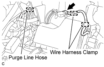
Separate the mass air flow meter connector and 2 wire harness clamps.
-
Separate the purge line hose.
-
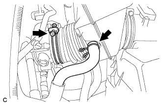
Separate the ventilation hose.
-
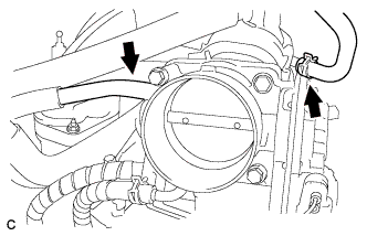
Loosen the hose clamp and separate the air cleaner hose from the throttle body.
-
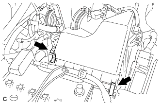
Release the 2 clamps and remove the air cleaner cap sub-assembly.
-
-
REMOVE INTAKE AIR SURGE TANK ASSEMBLY
-
Disconnect the union to connector tube hose.
-
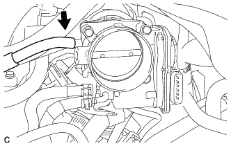
Disconnect the ventilation hose.
-
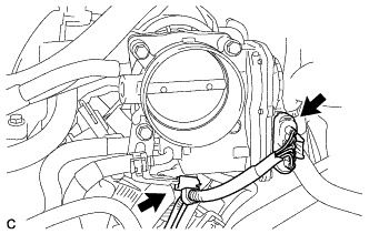
Disconnect the throttle body assembly connector and wire harness clamp.
-
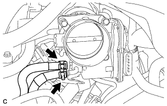
Disconnect the fuel vapor feed hose.
-
Disconnect the 2 water by-pass hoses.
-
Disconnect the connector from the intake air control valve assembly.
-
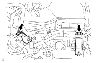
Remove the bolt and separate the No. 1 surge tank stay from the intake air surge tank assembly.
-
Remove the bolt and separate the throttle body bracket from the intake air surge tank assembly.
-

Remove the 2 nuts from the intake air surge tank assembly.
-
Using a 5 mm socket hexagon wrench, remove the 4 bolts.
-
Remove the intake air surge tank assembly and 3 air surge tank to intake manifold gaskets.
-
-
REMOVE NO. 1 SURGE TANK STAY
-
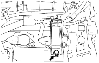
Remove the bolt and No. 1 surge tank stay.
-
-
REMOVE IGNITION COIL ASSEMBLY
-
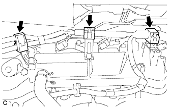
Disconnect the 3 wire harness clamps.
-
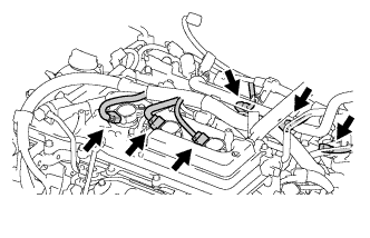
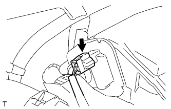
Disconnect the 6 ignition coil connectors.
-
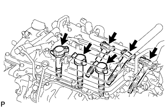
Remove the 6 bolts and 6 ignition coils.
-
-
REMOVE SPARK PLUG
-
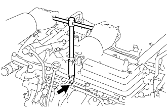
Remove the 6 spark plugs.
-