CYLINDER HEAD GASKET INSTALLATION

-
INSTALL CYLINDER HEAD GASKET
-
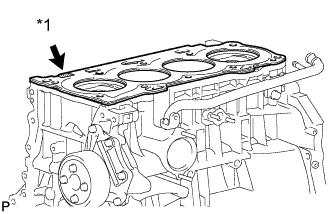
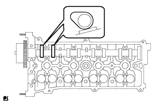
Text in Illustration *1 Lot No. Place a new cylinder head gasket on the cylinder block surface with the Lot No. stamp facing upward.
Note
-
Remove any oil from the contact surfaces.
-
Be careful of the installation direction.
-
-
-
INSTALL CYLINDER HEAD SUB-ASSEMBLY
-
Place the cylinder head on the cylinder head gasket.
Note
Place the cylinder head gently in order to avoid damaging the cylinder head gasket.
-
Install the cylinder head bolts.
Note
The cylinder head bolts are tightened in 2 successive steps.
-
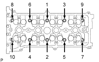
Apply a light coat of engine oil to the threads and under the heads of the cylinder head set bolts.
-
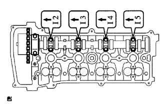
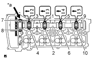
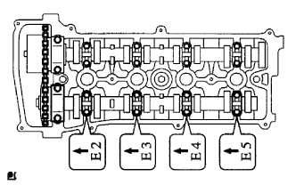
Using several steps, uniformly install and tighten the 10 cylinder head set bolts and plate washers with a 10 mm bi-hexagon wrench in the order shown in the illustration.
- Torque:
- 70 N*m { 714 kgf*cm, 52 ft.*lbf }
-
-
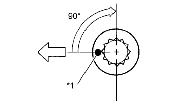
Text in Illustration *1 Paint Mark 
Engine Front Mark the front of the cylinder head bolts with paint.
-
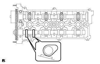
Further tighten the cylinder head bolts 90° as shown in the illustration.
-
Check that the paint mark is now at a 90° angle to the front.
-
-
INSTALL EXHAUST MANIFOLD CONVERTER SUB-ASSEMBLY
-
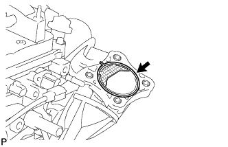
Install a new exhaust manifold to head gasket.
-
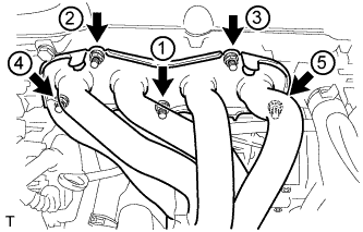
Using a 12 mm deep socket wrench, install the exhaust manifold converter sub-assembly and 5 nuts in the order shown in the illustration.
- Torque:
- 37 N*m { 377 kgf*cm, 27 ft.*lbf }
-
-
INSTALL NO. 2 MANIFOLD STAY
-
Install the No. 2 manifold stay with the bolt and nut.
- Torque:
- 44 N*m { 449 kgf*cm, 33 ft.*lbf }
-
-
INSTALL MANIFOLD STAY
-
Install the manifold stay with the bolt and nut.
- Torque:
- 44 N*m { 449 kgf*cm, 33 ft.*lbf }
-
-
INSTALL NO. 1 EXHAUST MANIFOLD HEAT INSULATOR
-
Install the No. 1 exhaust manifold heat insulator with the 4 bolts.
- Torque:
- 12 N*m { 122 kgf*cm, 9 ft.*lbf }
-
-
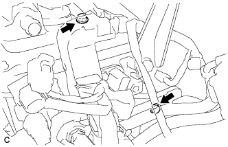
INSTALL INTAKE MANIFOLD
-
Install the vacuum hose clamp with the bolt.
- Torque:
- 8.5 N*m { 87 kgf*cm, 75 in.*lbf }
-
Install the union to check valve hose, No. 2 ventilation hose and No. 1 throttle body hose.
-
Install the No. 1 intake manifold insulator.
-
Install a new No. 1 intake manifold to head gasket.
-
Set the intake manifold.
-
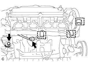
Connect the engine wire.
-
Connect the engine wire harness with the 2 bolts.
-
Connect the connector and wire harness clamp.
-
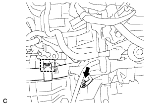
Install the earth bolt.
- Torque:
- 8.4 N*m { 86 kgf*cm, 74 in.*lbf }
-
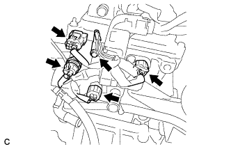
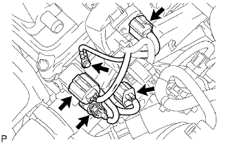
Connect the 4 connectors.
-
Connect the 4 connectors.
-
Install the earth bolt.
- Torque:
- 8.4 N*m { 86 kgf*cm, 74 in.*lbf }
-
Connect the connector and 3 wire harness clamps.
-
Connect the earth connector and wire harness clamp.
-
Connect the terminal B with the nut and install the terminal cap.
- Torque:
- 9.8 N*m { 100 kgf*cm, 87 in.*lbf }
-
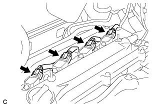
Connect the 2 connectors and 2 wire harness clamps.
-
Connect the compressor connector and clamp.
-
-
Using an E7 "TORX" wrench, install the 2 stud bolts.
- Torque:
- 9.5 N*m { 97 kgf*cm, 84 in.*lbf }
-
Install the intake manifold with the 5 bolts and 2 nuts.
- Torque:
- 30 N*m { 306 kgf*cm, 22 ft.*lbf }
-
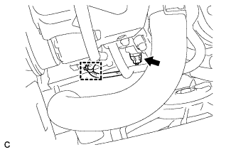
Connect the union to check valve hose to the hose clamp.
-
Connect the oxygen sensor connector and clamp.
-
-
INSTALL THROTTLE BODY ASSEMBLY
-
Install a new gasket onto the intake manifold.
-
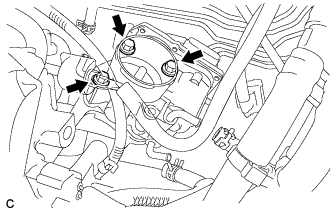
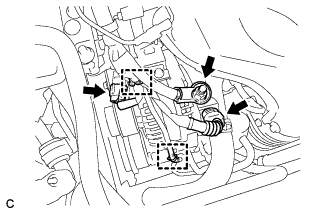
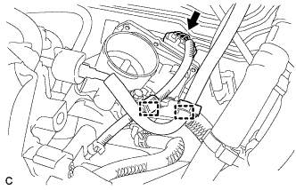
Temporarily install the throttle body assembly and fuel pipe support bracket with the 3 bolts.
-
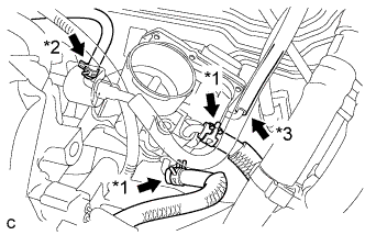
Connect the 2 water by-pass hoses. (*1).
-
Connect the purge line hose. (*2)
-
Connect the No. 1 throttle body hose. (*3)
-
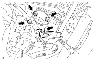
Install the fuel pipe support bracket and throttle body assembly with the 4 bolts.
- Torque:
- 30 N*m { 306 kgf*cm, 22 ft.*lbf }
-
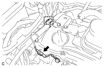
Connect the throttle body connector to the throttle body assembly.
-
Connect the wire harness clamp to the fuel pipe support bracket.
-
Install the hose to the fuel pipe support bracket.
-
-
INSTALL NO. 1 CAMSHAFT BEARING
-
Clean the installation surfaces of the cap and the inner and outer surfaces of the bearing.
Note
Keep the installation surfaces and the back surfaces of the bearing free of engine oil.
-
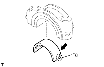
Text in Illustration *a Claw Align the claws and install the No. 1 camshaft bearing onto the No. 1 camshaft bearing cap.
-
-
INSTALL NO. 2 CAMSHAFT BEARING
-
Clean the installation surfaces of the cap and the inner and outer surfaces of the bearing.
Note
Keep the installation surfaces and the back surfaces of the bearing free of engine oil.
-
Install the No. 2 camshaft bearing onto the cylinder head.
-
-
INSTALL CAMSHAFT
-
Apply a light coat of engine oil to the journal portion.
-
Place the camshaft on the cylinder head with the No. 1 cam lobes facing the directions shown in the illustration.
-
Apply a light coat of engine oil to the threads and under the heads of the bearing cap bolts.
-
Examine the front marks and numbers, and check that the order is as shown in the illustration. Then install the bearing caps into the cylinder head.
-
Text in Illustration *a No. 1 Using several steps, uniformly tighten the 10 bearing cap bolts in the sequence shown in the illustration.
- Torque:
- No. 1 Bearing cap
- 30 N*m { 301 kgf*cm, 22 ft.*lbf }
- No. 3 Bearing cap
- 9.0 N*m { 92 kgf*cm, 80 in.*lbf }
-
-
INSTALL NO. 2 CAMSHAFT
-
Apply a light coat of engine oil to the journal portion of the No. 2 camshaft.
-
Place the camshaft on the cylinder head with the No. 2 cam lobes facing the directions shown in the illustration.
-
Apply a light coat of engine oil to the threads and under the heads of the bearing cap bolts.
-
Examine the front marks and numbers, and check that the order is as shown in the illustration. Then install the bearing caps onto the cylinder head.
-
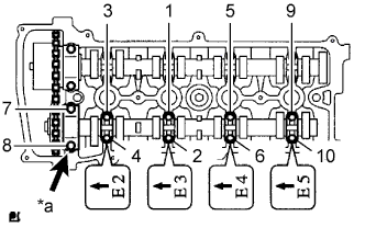
Text in Illustration *a No. 2 Using several steps, uniformly tighten the 10 bearing cap bolts in the sequence shown in the illustration.
- Torque:
- No. 2 Bearing cap
- 30 N*m { 301 kgf*cm, 22 ft.*lbf }
- No. 3 Bearing cap
- 9.0 N*m { 92 kgf*cm, 80 in.*lbf }
-
-
CONNECT ENGINE WIRE
-
Connect the ground cable with the bolt.
- Torque:
- 8.4 N*m { 86 kgf*cm, 74 in.*lbf }
-
Connect the camshaft position sensor connector.
-
Connect the engine coolant temperature sensor connector.
-
Connect the engine oil pressure switch connector.
-
Connect the radio setting condenser connector.
-
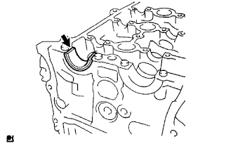
Connect the heater water inlet hose.
-
-
INSTALL NO. 1 CHAIN VIBRATION DAMPER
-
Install the No. 1 chain vibration damper with the 2 bolts.
- Torque:
- 9.0 N*m { 92 kgf*cm, 80 in.*lbf }
-
-
INSTALL CHAIN SUB-ASSEMBLY
-
Set the No. 1 cylinder to TDC/compression.
-

Text in Illustration *1 Timing Mark Turn the camshafts with a wrench (using the hexagonal lobe) to align the timing marks on the camshaft timing gear with the timing marks located on the No. 1 and No. 2 bearing caps as shown in the illustration.
-
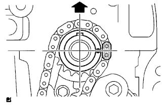
Using the crankshaft pulley bolt, turn the crankshaft to position the key on the crankshaft upward.
-
-
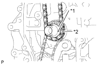
Text in Illustration *1 Timing Mark *2 Mark Link Install the chain onto the crankshaft timing sprocket with the gold or orange mark link aligned with the timing mark on the crankshaft.
-
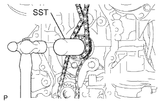
Using SST and a hammer, tap in the crankshaft timing sprocket.
- SST
- 09309-37010
-
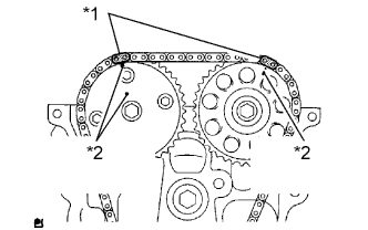
Text in Illustration *1 Mark Link *2 Timing Mark Align the gold or yellow links with the timing marks located on the camshaft timing gear and sprocket, then install the chain.
-
-
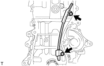
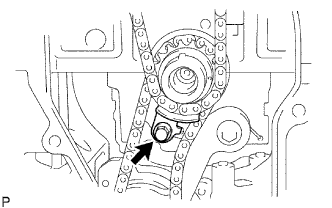
INSTALL CHAIN TENSIONER SLIPPER
-
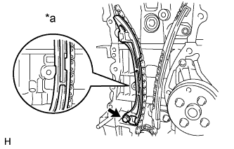
Text in Illustration *a Hold Install the chain tensioner slipper with the bolt.
- Torque:
- 19 N*m { 194 kgf*cm, 14 ft.*lbf }
-
-
INSTALL TIMING CHAIN GUIDE
-
Install the timing chain guide with the bolt.
- Torque:
- 9.0 N*m { 92 kgf*cm, 80 in.*lbf }
-
-
INSTALL NO. 1 CRANKSHAFT POSITION SENSOR PLATE
-
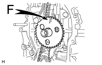
Install the sensor plate with the "F" mark facing forward.
-
-
INSTALL TIMING CHAIN OR BELT COVER SUB-ASSEMBLY
Tech Tips
See the steps from "Install Timing Chain or Belt Cover Sub-Assembly" through "Install Continuously Variable Transaxle Assembly" Click here.