CYLINDER HEAD GASKET REMOVAL

-
REMOVE TIMING CHAIN OR BELT COVER SUB-ASSEMBLY
Tech Tips
See the steps from "Remove Continuously Variable Transaxle Assembly" through "Remove Timing Chain or Belt Cover Sub-Assembly" Click here.
-
REMOVE NO. 1 CRANKSHAFT POSITION SENSOR PLATE
-
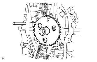
Remove the No. 1 crankshaft position sensor plate.
-
-
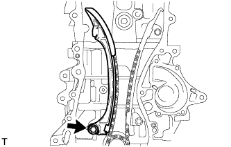
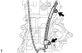
REMOVE TIMING CHAIN GUIDE
-
Remove the bolt and timing chain guide.
-
-
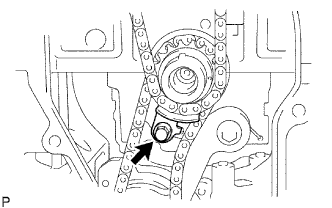
REMOVE CHAIN TENSIONER SLIPPER
-
Remove the bolt and chain tensioner slipper.
-
-
REMOVE NO. 1 CHAIN VIBRATION DAMPER
-
Remove the 2 bolts and No. 1 chain vibration damper.
-
-
REMOVE CHAIN SUB-ASSEMBLY
-
Remove the chain sub-assembly.
-
-
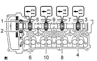
REMOVE NO. 2 CAMSHAFT
-
Using several steps, uniformly loosen and remove the 10 bearing cap bolts in the sequence shown in the illustration.
Note
Uniformly loosen the bolts while keeping the camshaft level.
Tech Tips
Arrange the removed parts in the correct order.
-
Remove the 5 bearing caps.
-
Remove the No. 2 camshaft.
-
-
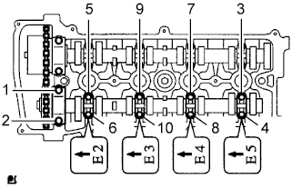
REMOVE CAMSHAFT
-
Using several steps, uniformly loosen and remove the 10 bearing cap bolts in the sequence shown in the illustration.
Note
Uniformly loosen the bolts while keeping the camshaft level.
Tech Tips
Arrange the removed parts in the correct order.
-
Remove the 5 bearing caps.
-
Remove the camshaft.
-
-
REMOVE NO. 1 CAMSHAFT BEARING
-
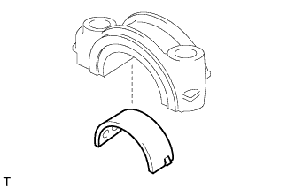
Remove the camshaft bearing from the No. 1 camshaft bearing cap.
-
-
REMOVE NO. 2 CAMSHAFT BEARING
-
Clean the installation surfaces of the cap and the inner and outer surfaces of the bearing.
Note
Keep the installation surfaces and the back surfaces of the bearing free of engine oil.
-
Install the No. 2 camshaft bearing onto the cylinder head.
-
-
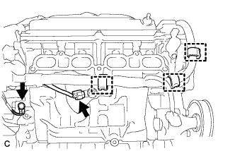
DISCONNECT ENGINE WIRE
-
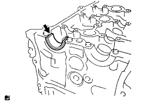
Disconnect the bolt and ground cable.
-
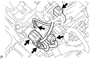
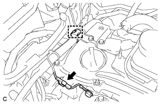
Disconnect the camshaft position sensor connector.
-
Disconnect the engine coolant temperature sensor connector.
-
Disconnect the radio setting condenser connector.
-
Disconnect the engine oil pressure switch connector.
-
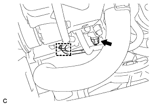
Disconnect the heater water inlet hose.
-
-
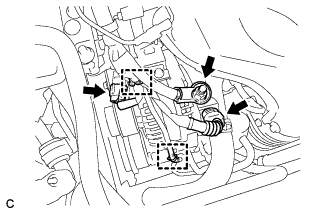
REMOVE THROTTLE BODY ASSEMBLY
-
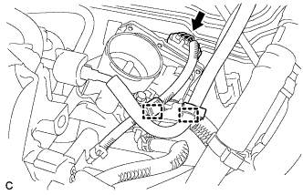
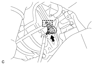
Disconnect the wire harness clamp and throttle body connector.
-
Disconnect the fuel hose clamp from the fuel pipe support bracket.
-
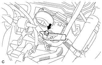
Remove the bolt and fuel pipe support bracket.
-
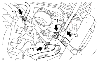
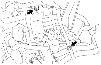
Disconnect the 2 water by-pass hoses. (*1)
-
Disconnect the purge line hose. (*2)
-
Disconnect the No. 1 throttle body hose. (*3)
-
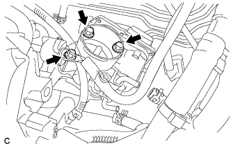
Remove the 3 bolts and throttle body assembly.
-
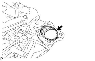
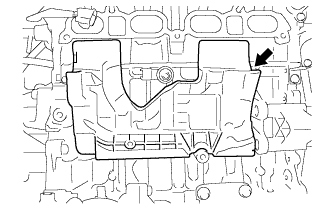
Remove the gasket from the intake manifold.
-
-
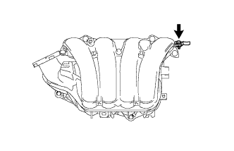
REMOVE INTAKE MANIFOLD
-
Disconnect the oxygen sensor connector and clamp.
-
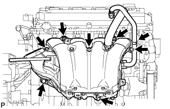
Disconnect the union to check valve hose from the hose clamp.
-
Remove the 5 bolts and 2 nuts, and separate the intake manifold.
-
Using an E7 "TORX" wrench, remove the 2 stud bolts.
-
Disconnect the engine wire.
-
Disconnect the compressor connector and clamp.
-
Disconnect the 2 connectors and 2 wire harness clamps.
-
Remove the terminal cap and nut, and disconnect the terminal B.
-
Disconnect the earth connector and wire harness clamp.
-
Disconnect the connector and 3 wire harness clamps.
-
Remove the earth bolt.
-
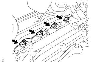
Disconnect the 4 connectors.
-
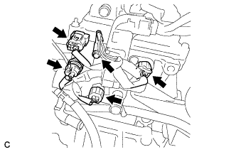
Disconnect the 4 connectors.
-
Remove the earth bolt.
-
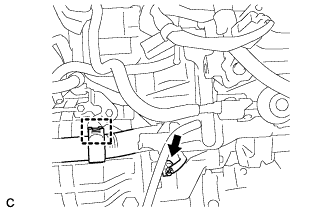
Disconnect the connector and wire harness clamp.
-
Remove the 2 bolts and disconnect the engine wire harness.
-
-
Remove the No. 1 intake manifold insulator.
-
Remove the intake manifold.
-
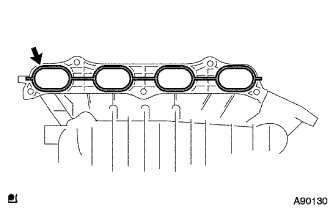
Remove the No. 1 intake manifold to head gasket.
-
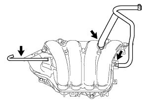
Remove the union to check valve hose, No. 2 ventilation hose and No. 1 throttle body hose.
-
Remove the bolt and vacuum hose clamp.
-
-
REMOVE NO. 1 EXHAUST MANIFOLD HEAT INSULATOR
-
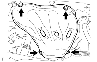
Remove the 4 bolts and No. 1 exhaust manifold heat insulator.
-
-
REMOVE MANIFOLD STAY
-
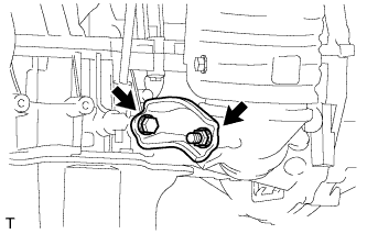
Remove the bolt, nut and manifold stay.
-
-
REMOVE NO. 2 MANIFOLD STAY
-
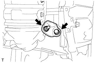
Remove the bolt, nut and No. 2 manifold stay.
-
-
REMOVE EXHAUST MANIFOLD CONVERTER SUB-ASSEMBLY
-
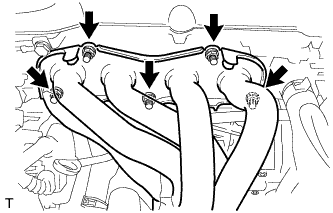
Using a 12 mm deep socket wrench, remove the 5 nuts and exhaust manifold converter sub-assembly.
-
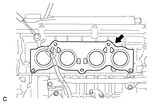
Remove the exhaust manifold to head gasket.
-
-
REMOVE CYLINDER HEAD SUB-ASSEMBLY
-
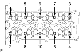
In several steps, uniformly loosen and remove the 10 cylinder head bolts and 10 plate washers with a 10 mm bi-hexagon wrench in the sequence shown in the illustration.
Note
Head warpage or cracking could result from removing the bolts in the wrong order.
-
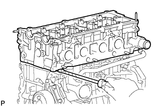
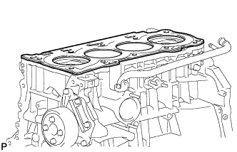
Using a screwdriver with its tip wrapped with tape, pry between the cylinder head and cylinder block, and remove the cylinder head.
Note
Be careful not to damage the contact surfaces between the cylinder head and cylinder block.
-
-
REMOVE CYLINDER HEAD GASKET