VALVE CLEARANCE ADJUSTMENT

-
REMOVE ENGINE UNDER COVER RH
-
REMOVE IGNITION COIL ASSEMBLY
-
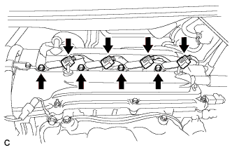
Disconnect the 4 ignition coil connectors.
-
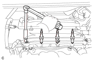
Remove the 4 bolts and 4 ignition coils.
-
-
REMOVE SPARK PLUG
-
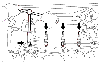
Remove the 4 spark plugs.
-
-
REMOVE CYLINDER HEAD COVER SUB-ASSEMBLY
-
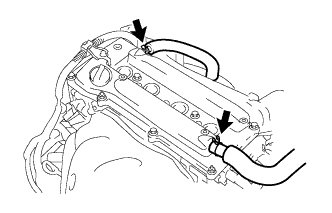
Remove the 2 ventilation hoses from the cylinder head cover sub-assembly.
-
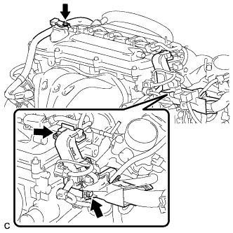
Remove the 3 bolts and separate the wire harness.
-
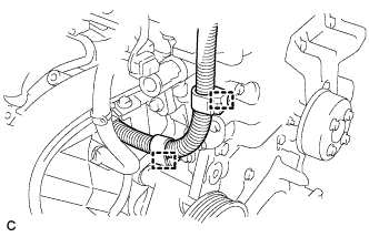
Disconnect the 2 wire harness clamps.
-
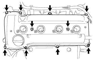
Remove the 8 bolts and 2 nuts, then remove the cylinder head cover sub-assembly and gasket.
-
-
SET NO. 1 CYLINDER TO TDC/COMPRESSION
-
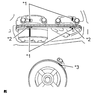
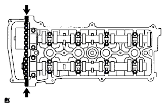
Text in Illustration *1 Timing Mark *2 Paint Mark *3 Groove Turn the crankshaft pulley until the groove and the timing mark "0" on the timing chain cover are aligned.
-
Check that each timing mark on the camshaft timing gear and sprocket is aligned with each timing mark located on the No. 1 and No. 2 bearing caps as shown in the illustration.
If not, turn the crankshaft pulley 1 revolution (360°) to align the timing marks as illustrated.
-
Place paint marks on the chain in alignment with the timing marks on the camshaft timing gear and camshaft timing sprocket.
-
-
CHECK VALVE CLEARANCE
-
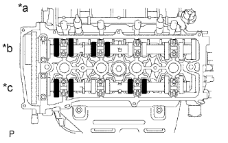
Text in Illustration *a No. 1 Cylinder TDC/Compression *b Intake *c Exhaust Check only the valves indicated in the illustration.
-
Using a feeler gauge, measure the clearance between the valve lifter and camshaft.
Standard Valve Clearance (Cold) Item Specified Condition Intake 0.19 to 0.29 mm (0.00748 to 0.0114 in.) Exhaust 0.38 to 0.48 mm (0.0150 to 0.0189 in.) -
Record any out-of-specification valve clearance measurements. They will be used later to determine the required replacement valve clearance lifters.
-
-
Turn the crankshaft 1 revolution (360°) and set the No. 4 cylinder to TDC/Compression.
-
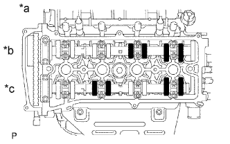
Text in Illustration *a No. 4 Cylinder TDC/Compression *b Intake *c Exhaust Check only the valves indicated in the illustration.
-
Using a feeler gauge, measure the clearance between the valve lifter and camshaft.
Standard Valve Clearance (Cold) Item Specified Condition Intake 0.19 to 0.29 mm (0.00748 to 0.0114 in.) Exhaust 0.38 to 0.48 mm (0.0150 to 0.0189 in.) -
Record any out-of-specification valve clearance measurements. They will be used later to determine the required replacement valve lifters.
-
-
-
ADJUST VALVE CLEARANCE
-
Set No. 1 cylinder to TDC/compression Click here.
-
Remove the No. 1 chain tensioner Click here.
-
Loosen the camshaft timing sprocket Click here.
-
Remove the No. 2 camshaft Click here.
-
Remove the camshaft Click here.
-
Remove the valve lifters.
-
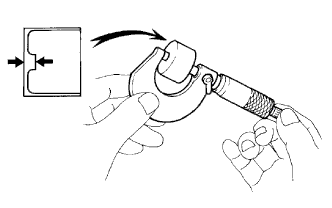
Using a micrometer, measure the thickness of the removed valve lifters.
-
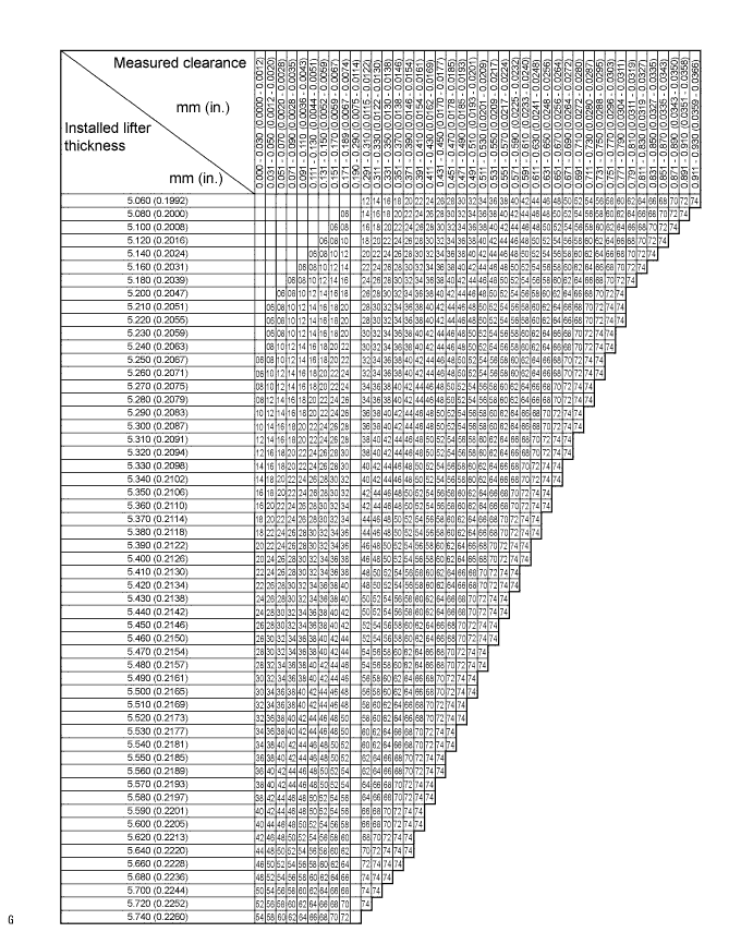
Calculate the thickness of a new lifter so that the valve clearance comes within the specified values.
New Lifter Thickness Item Specification Intake A = B + (C - 0.24 mm (0.00945 in.)) Exhaust A = B + (C - 0.43 mm (0.0169 in.)) A New lifter thickness B Used lifter thickness C Measured valve clearance CALCULATION EXAMPLE (Intake):
-
Measured intake valve clearance = 0.40 mm (0.0157 in.)
(Measured - Specification = Excess clearance)
-
0.40 mm (0.0157 in.) - 0.24 mm (0.00945 in.) = 0.16 mm (0.00630 in.)
-
Measured used lifter thickness = 5.250 mm (0.2067 in.)
-
New lifter thickness = 5.410 mm (0.2130 in.)
(Excess clearance + Used lifter thickness = Ideal new lifter)
-
0.16 mm (0.00630 in.) + 5.250 mm (0.2067 in.) = 5.410 mm (0.2130 in.)
-
Closest new lifter = 5.420 mm (0.2134 in.)
-
Select No. 42 lifter
-
-
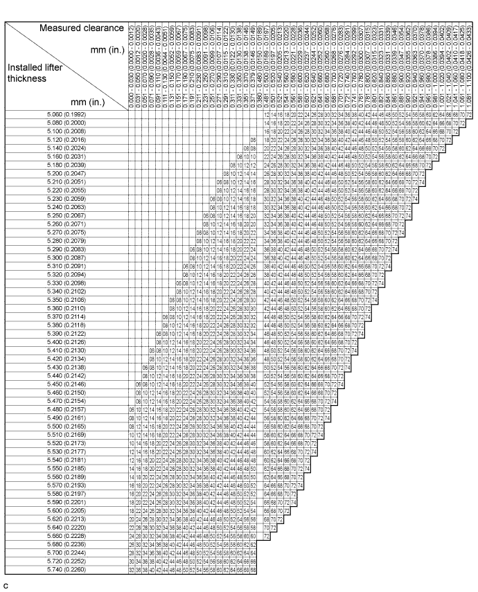
Select a new lifter with a thickness as close as possible to the calculated values.
Tech Tips
-
Lifters are available in 35 sizes in increments of 0.020 mm (0.000787 in.), from 5.060 to 5.740 mm (0.1992 to 0.2260 in.).
-
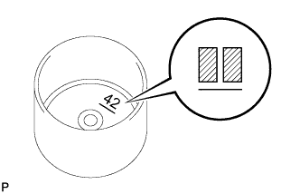
The identification number inside the valve lifters shows the value to 2 decimal places. (The illustration shows 5.420 mm (0.2134 in.)
-
-
Valve lifter selection chart (intake).
New Lifter Thickness Lifter No. Thickness
mm (in.)
Lifter No. Thickness
mm (in.)
Lifter No. Thickness
mm (in.)
06 5.060 (0.1992) 30 5.300 (0.2087) 54 5.540 (0.2181) 08 5.080 (0.2000) 32 5.320 (0.2094) 56 5.560 (0.2189) 10 5.100 (0.2008) 34 5.340 (0.2102) 58 5.580 (0.2197) 12 5.120 (0.2016) 36 5.360 (0.2110) 60 5.600 (0.2205) 14 5.140 (0.2024) 38 5.380 (0.2118) 62 5.620 (0.2213) 16 5.160 (0.2031) 40 5.400 (0.2126) 64 5.640 (0.2220) 18 5.180 (0.2039) 42 5.420 (0.2134) 66 5.660 (0.2228) 20 5.200 (0.2047) 44 5.440 (0.2142) 68 5.680 (0.2236) 22 5.220 (0.2055) 46 5.460 (0.2150) 70 5.700 (0.2244) 24 5.240 (0.2063) 48 5.480 (0.2157) 72 5.720 (0.2252) 26 5.260 (0.2071) 50 5.500 (0.2165) 74 5.740 (0.2260) 28 5.280 (0.2079) 52 5.520 (0.2173) - - Standard intake valve clearance (cold) 0.19 to 0.29 mm (0.00748 to 0.0114 in.) EXAMPLE:
The 5.250 mm (0.2067 in.) lifter is installed, and the measured clearance is 0.400 mm (0.0157 in.). Replace the 5.250 mm (0.2067 in.) lifter with a new No. 42 lifter.
-
Valve lifter selection chart (exhaust).
New Lifter Thickness Lifter No. Thickness
mm (in.)
Lifter No. Thickness
mm (in.)
Lifter No. Thickness
mm (in.)
06 5.060 (0.1992) 30 5.300 (0.2087) 54 5.540 (0.2181) 08 5.080 (0.2000) 32 5.320 (0.2094) 56 5.560 (0.2189) 10 5.100 (0.2008) 34 5.340 (0.2102) 58 5.580 (0.2197) 12 5.120 (0.2016) 36 5.360 (0.2110) 60 5.600 (0.2205) 14 5.140 (0.2024) 38 5.380 (0.2118) 62 5.620 (0.2213) 16 5.160 (0.2031) 40 5.400 (0.2126) 64 5.640 (0.2220) 18 5.180 (0.2039) 42 5.420 (0.2134) 66 5.660 (0.2228) 20 5.200 (0.2047) 44 5.440 (0.2142) 68 5.680 (0.2236) 22 5.220 (0.2055) 46 5.460 (0.2150) 70 5.700 (0.2244) 24 5.240 (0.2063) 48 5.480 (0.2157) 72 5.720 (0.2252) 26 5.260 (0.2071) 50 5.500 (0.2165) 74 5.740 (0.2260) 28 5.280 (0.2079) 52 5.520 (0.2173) - - Standard exhaust valve clearance (cold) 0.38 to 0.48 mm (0.0150 to 0.0189 in.) EXAMPLE:
The 5.340 mm (0.2102 in.) lifter is installed, and the measured clearance is 0.510 mm (0.0201 in.). Replace the 5.340 mm (0.2102 in.) lifter with a new No. 42 lifter.
-
Install the selected valve lifter.
-
Install the camshaft Click here.
-
Install the No. 2 camshaft Click here.
-
Install the No. 1 chain tensioner Click here.
-
-
INSTALL CYLINDER HEAD COVER SUB-ASSEMBLY
-
Remove any old packing material from the contact surfaces.
-
Apply seal packing to the 2 locations shown in the illustration.
Seal packing Toyota Genuine Seal Packing Black, Three Bond 1207B or equivalent Note
-
Remove any oil from the contact surfaces.
-
Install the oil pan within 3 minutes of applying seal packing.
-
Do not add engine oil for at least 2 hours after installing the oil pan.
-
-
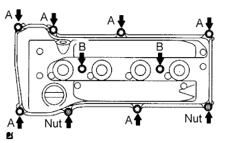
Install the cylinder head cover gasket and sub-assembly with the 8 bolts and 2 nuts.
- Torque:
- Bolt A
- 11 N*m { 112 kgf*cm, 8 ft.*lbf }
- Bolt B
- 14 N*m { 143 kgf*cm, 10 ft.*lbf }
- Nut
- 11 N*m { 112 kgf*cm, 8 ft.*lbf }
-
Install the engine wire harness with the 3 bolts.
- Torque:
- 8.4 N*m { 86 kgf*cm, 74 in.*lbf }
-
Connect the 2 wire harness clamps.
-
Connect the 2 ventilation hoses to the cylinder head cover.
-
-
INSTALL SPARK PLUG
-
Install the 4 spark plugs.
- Torque:
- 19 N*m { 194 kgf*cm, 14 ft.*lbf }
-
-
INSTALL IGNITION COIL ASSEMBLY
-
Install the 4 ignition coils with the 4 bolts.
- Torque:
- 9.0 N*m { 92 kgf*cm, 80 in.*lbf }
-
Connect the 4 ignition coil connectors.
-
-
INSPECT FOR OIL LEAK
-
INSPECT IGNITION TIMING
Note
-
Turn all the electrical systems and the A/C off.
-
When checking the ignition timing, the transaxle should be in neutral or park.
-
Warm up and stop the engine.
-
When using the intelligent tester:
-
Connect the intelligent tester to the DLC3.
-
Turn the engine switch on (IG).
-
Turn the intelligent tester on.
-
Enter the following menus: Power Train / Engine and ECT / Data List / IGN Advance
-
Start the engine.
-
According to the display on the intelligent tester, read the Data List.
Standard ignition timing 8 to 16° BTDC at idle -
Check that the ignition timing advances immediately when the engine speed is increased.
-
Turn the engine switch off.
-
Disconnect the intelligent tester from the DLC3.
-
-
When not using the intelligent tester:
-
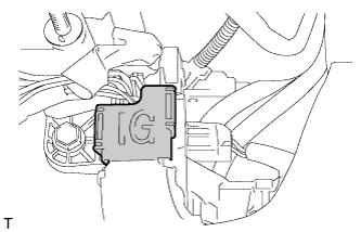
Open the ignition cover located to the right of the No. 4 ignition coil.
-
Pull the wire harness out from the IG cover.
-
Connect the timing light to the wire harness.
Note
Use a timing light that detects the primary signal.
-
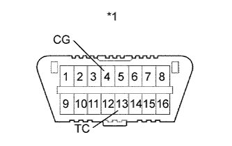
Text in Illustration *1 DLC3 Using SST, connect terminals 13 (TC) and 4 (CG) of the DLC3.
- SST
- 09843-18040
-
Allow the engine to idle and check the ignition timing.
Standard ignition timing 8 to 12° BTDC at idle Tech Tips
Run the engine at 1000 to 1300 rpm for 5 seconds, then check that the engine speed returns to idle speed.
-
Disconnect SST from terminals 13 (TC) and 4 (CG) of the DLC3.
-
Allow the engine to idle and check the ignition timing.
Standard ignition timing 8 to 16° BTDC at idle -
Check that the ignition timing advances immediately when the engine speed is increased.
-
Turn the engine switch off.
-
Remove the timing light.
-
Close the IG cover.
-
-
-
INSTALL ENGINE UNDER COVER RH