INSPECTION PROCEDURE
PROCEDURE
- Click here
CHECK FUEL PUMP OPERATION
-
Check the fuel pump operation (Click here).
- OKClick here
- NGClick here
-
- Click here
INSPECT F/PMP RELAY
-
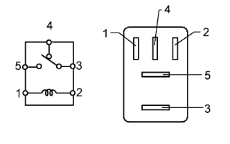
Remove the F/PMP relay from the engine room relay block.
-
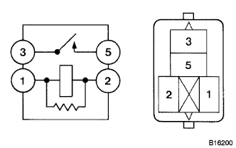
Measure the resistance according to the value(s) in the table below.
Standard Resistance Tester Connection Condition Specified Condition 3 - 4 No battery voltage applied to terminals 1 and 2 Below 1 Ω 3 - 4 Battery voltage applied to terminals 1 and 2 10 kΩ or higher 3 - 5 No battery voltage applied to terminals 1 and 2 10 kΩ or higher 3 - 5 Battery voltage applied to terminals 1 and 2 Below 1 Ω -
Reinstall the F/PMP relay.
- OKClick here
- NGClick here
-
- Click here
INSPECT FUEL PUMP RESISTOR
-
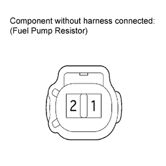
Disconnect the fuel pump resistor connector.
-
Measure the resistance according to the value(s) in the table below.
Standard Resistance Tester Connection Condition Specified Condition 1 - 2 20°C (68°F) 0.30 to 0.34 Ω -
Reconnect the fuel pump resistor connector.
- OKClick here
- NGClick here
-
- Click here
CHECK HARNESS AND CONNECTOR (F/PMP RELAY - FUEL PUMP RESISTOR)
-
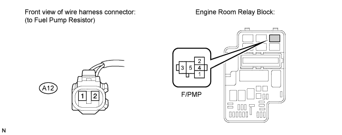
Remove the F/PMP relay from the engine room relay block.
-
Disconnect the fuel pump resistor connector.
-
Measure the resistance according to the value(s) in the table below.
Standard Resistance (Check for Open) Tester Connection Condition Specified Condition 5 (F/PMP relay) - A12-1 (Fuel pump resistor) Always Below 1 Ω 4 (F/PMP relay) - A12-2 (Fuel pump resistor) Always Below 1 Ω Standard Resistance (Check for Short) Tester Connection Condition Specified Condition 5 (Fuel pump relay) or A12-1 (Fuel pump resistor) - Body ground Always 10 kΩ or higher 4 (Fuel pump relay) or A12-2 (Fuel pump resistor) - Body ground Always 10 kΩ or higher -
Reinstall the F/PMP relay.
-
Reconnect the fuel pump resistor connector.
- OKClick here
- NGClick here
-
- Click here
PERFORM ACTIVE TEST USING INTELLIGENT TESTER (OPERATE CIRCUIT OPENING RELAY)
-
Connect the intelligent tester to the DLC3.
-
Turn the engine switch on (IG) and turn the tester on.
-
Enter the following menus: Powertrain / Engine / Active Test /Activate the Fuel Pump Speed Control.
-
Check the operation of the relay while operating it using the tester.
OK Operating noise can be heard from the relay.
- OKClick here
- NGClick here
-
- Click here
INSPECT FUEL PUMP
-
Inspect the fuel pump (Click here).
- OKClick here
- NGClick here
-
- Click here
CHECK HARNESS AND CONNECTOR (FUEL PUMP - F/PMP RELAY)
-
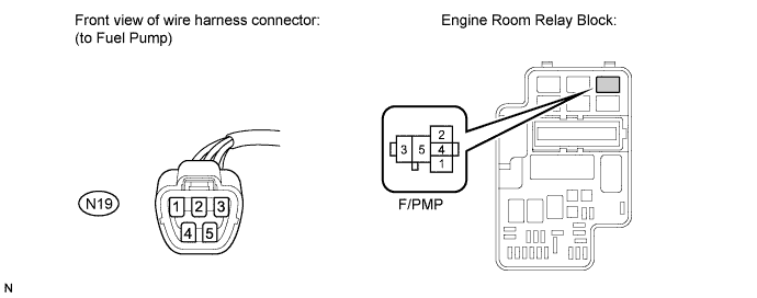
Disconnect the fuel pump connector.
-
Remove the F/PMP relay from the engine room relay block.
-
Measure the resistance according to the value(s) in the table below.
Standard Resistance (Check for Open) Tester Connection Condition Specified Condition N19-4 (Fuel pump) - 4 (F/PMP relay) Always Below 1 Ω Standard Resistance (Check for Short) Tester Connection Condition Specified Condition N19-4 (Fuel pump) or 4 (F/PMP) - Body ground Always 10 kΩ or higher -
Reinstall the F/PMP relay.
-
Reconnect the fuel pump connector.
- OKClick here
- NGClick here
-
- Click here
INSPECT RELAY BLOCK ASSEMBLY (C/OPN RELAY - F/PMP RELAY)
-
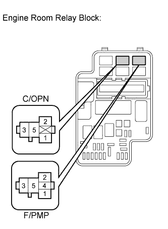
Remove the C/OPN relay from the engine room relay block.
-
Remove the F/PMP relay from the engine room relay block.
-
Measure the resistance according to the value(s) in the table below.
Standard Resistance (Check for Open) Tester Connection Condition Specified Condition 3 (C/OPN relay) - 2 (F/PMP relay) Always Below 1 Ω 3 (C/OPN relay) - 3 (F/PMP relay) Always Below 1 Ω Standard Resistance (Check for Short) Tester Connection Condition Specified Condition 3 (C/OPN relay) or 2 (F/PMP relay) - Body ground Always 10 kΩ or higher 3 (C/OPN relay) or 3 (F/PMP relay) - Body ground Always 10 kΩ or higher -
Reinstall the C/OPN relay.
-
Reinstall the F/PMP relay.
- OKClick here
- NGClick here
-
- Click here
CHECK HARNESS AND CONNECTOR (FUEL PUMP - BODY GROUND)
-

Disconnect the fuel pump connector.
-
Measure the resistance according to the value(s) in the table below.
Standard Resistance Tester Connection Condition Specified Condition N19-5 (Fuel pump) - Body ground Always Below 1 Ω -
Reconnect the fuel pump connector.
- OKClick here
- NGClick here
-
- Click here
CHECK FUEL LINE
-
Check the fuel lines for leaks or blockage.
OK No leaks or blockage
- OKClick here
- NGClick here
-
- Click here
INSPECT RELAY (C/OPN RELAY)
-
Remove the C/OPN relay from the engine room relay block.
-
Measure the resistance according to the value(s) in the table below.
Standard Resistance Tester Connection Condition Specified Condition 3 - 5 No battery voltage applied to terminals 1 and 2 10 kΩ or higher 3 - 5 Battery voltage applied to terminals 1 and 2 Below 1 Ω -
Reinstall the C/OPN relay.
- OKClick here
- NGClick here
-
- Click here
CHECK HARNESS AND CONNECTOR (C/OPN VOLTAGE)
-
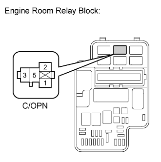
Remove the C/OPN relay from the engine room relay block.
-
Turn the engine switch on (IG).
-
Measure the voltage according to the value(s) in the table below.
Standard Voltage Tester Connection Switch Condition Specified Condition 5 (C/OPN relay) - Body ground Engine switch on (IG) 11 to 14 V 1 (C/OPN relay) - Body ground Engine switch on (IG) 11 to 14 V -
Reinstall the C/OPN relay.
- OKClick here
- NGClick here
-
- Click here
CHECK HARNESS AND CONNECTOR (C/OPN RELAY - ECM)
-
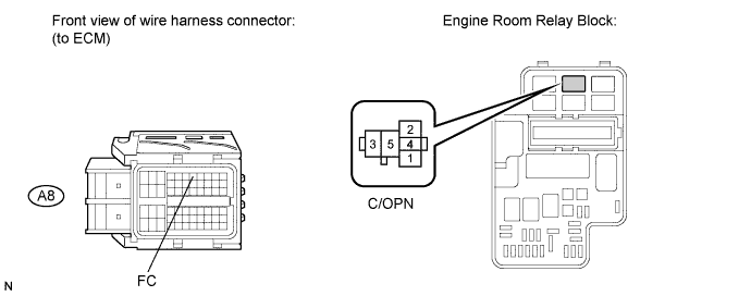
Remove the C/OPN relay from the engine room relay block.
-
Disconnect the ECM connector.
-
Measure the resistance according to the value(s) in the table below.
Standard Resistance (Check for Open) Tester Connection Condition Specified Condition 2 (C/OPN relay) - A8-7 (FC) Always Below 1 Ω Standard Resistance (Check for Short) Tester Connection Condition Specified Condition 2 (C/OPN relay) or A8-7 (FC) - Body ground Always 10 kΩ or higher -
Reconnect the ECM connector.
-
Reinstall the C/OPN relay.
- OKClick here
- NGClick here
-
- Click here
REPLACE F/PMP RELAY
- Click here
REPLACE FUEL PUMP RESISTORClick here
- Click here
REPAIR OR REPLACE HARNESS OR CONNECTOR (F/PMP RELAY - FUEL PUMP RESISTOR)
- Click here
PROCEED TO NEXT SUSPECTED AREA SHOWN IN PROBLEM SYMPTOMS TABLEClick here
- Click here
REPLACE FUEL PUMPClick here
- Click here
REPAIR OR REPLACE HARNESS OR CONNECTOR (FUEL PUMP - F/PMP RELAY)
- Click here
REPLACE ENGINE ROOM RELAY BLOCK
- Click here
REPAIR OR REPLACE HARNESS OR CONNECTOR (FUEL PUMP - BODY GROUND)
- Click here
REPAIR OR REPLACE FUEL LINE
- Click here
REPAIR OR REPLACE FUEL SYSTEM (PRESSURE REGULATOR AND FUEL FILTER)
- Click here
REPLACE RELAY (C/OPN RELAY)
- Click here
CHECK ECM POWER SOURCE CIRCUITClick here
- Click here
REPAIR OR REPLACE HARNESS OR CONNECTOR (C/OPN RELAY - ECM)
- Click here
REPLACE ECMClick here