SFI SYSTEM ECM Power Source Circuit
DESCRIPTION
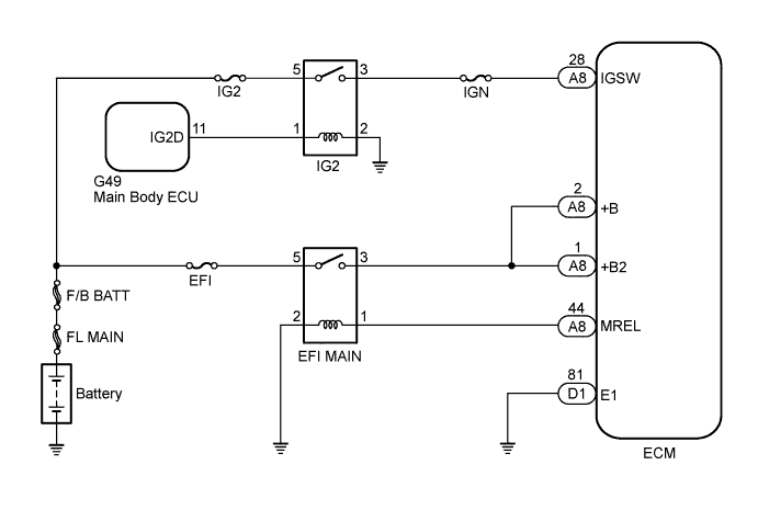
When the engine switch is turned on (IG), battery voltage is applied to terminal IGSW of the ECM. The ECM MREL output signal causes a current to flow to the coil, closing the contacts of the EFI MAIN relay and supplying power to terminals +B and +B2 of the ECM.
WIRING DIAGRAM
INSPECTION PROCEDURE
PROCEDURE
-
CHECK HARNESS AND CONNECTOR (ECM - BODY GROUND)
-
Disconnect the ECM connector.
-
Measure the resistance according to the value(s) in the table below.
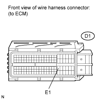
Standard Resistance Tester Connection Condition Specified Condition D1-81 (E1) - Body ground Always Below 1 Ω -
Reconnect the ECM connector.
NG 
REPAIR OR REPLACE HARNESS OR CONNECTOR (ECM - BODY GROUND)
OK 
-
-
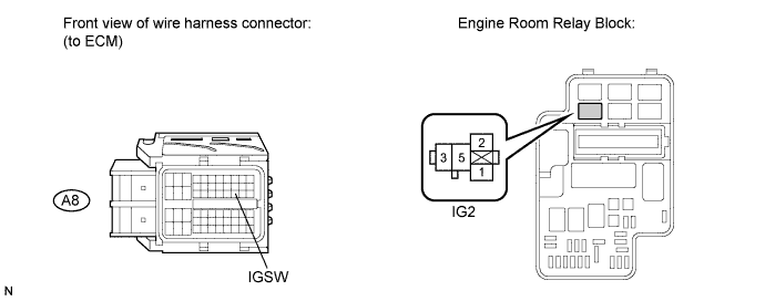
INSPECT ECM (IGSW VOLTAGE)
-
Disconnect the ECM connector.
-
Turn the engine switch on (IG).
-
Measure the voltage according to the value(s) in the table below.
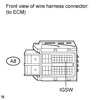
Standard Voltage Tester Connection Switch Condition Specified Condition A8-28 (IGSW) - Body ground Engine switch on (IG) 11 to 14 V -
Reconnect the ECM connector.
NG 
CHECK FUSE (IGN FUSE) Click here
OK
-
-
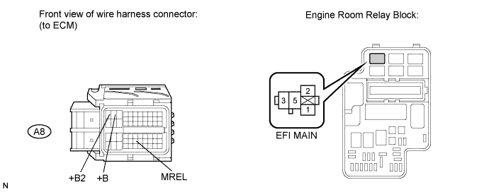
CHECK HARNESS AND CONNECTOR (EFI MAIN RELAY VOLTAGE)
-
Remove the EFI MAIN relay from the engine room relay block.
-
Measure the voltage according to the value(s) in the table below.
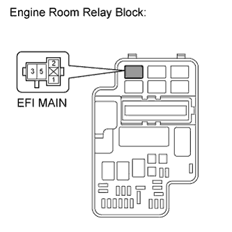
Standard Voltage Tester Connection Condition Specified Condition 5 (EFI MAIN relay) - Body ground Always 11 to 14 V -
Reinstall the EFI MAIN relay.
NG
CHECK FUSE (EFI FUSE) Click here
OK
-
-
INSPECT RELAY (EFI MAIN RELAY)
-
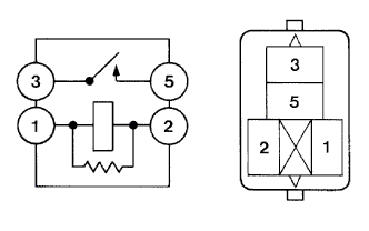
Remove the EFI MAIN relay from the engine room relay block.
-
Measure the resistance according to the value(s) in the table below.
Standard Resistance Tester Connection Condition Specified Condition 3 - 5 No battery voltage applied to terminals 1 and 2 10 kΩ or higher 3 - 5 Battery voltage applied to terminals 1 and 2 Below 1 Ω -
Reinstall the EFI MAIN relay.
NG
REPLACE EFI MAIN RELAY
OK
-
-
CHECK HARNESS AND CONNECTOR (EFI MAIN RELAY - ECM)
-
Remove the EFI MAIN relay from the engine room relay block.
-
Disconnect the ECM connector.
-
Measure the resistance according to the value(s) in the table below.
Standard Resistance (Check for Open) Tester Connection Condition Specified Condition 1 (EFI MAIN relay) - A8-44 (MREL) Always Below 1 Ω 3 (EFI MAIN relay) - A8-2 (+B) Always Below 1 Ω 3 (EFI MAIN relay) - A8-1 (+B2) Always Below 1 Ω Standard Resistance (Check for Short) Tester Connection Condition Specified Condition 1 (EFI MAIN relay) or A8-44 (MREL) - Body ground Always 10 kΩ or higher 3 (EFI MAIN relay) or A8-2 (+B) - Body ground Always 10 kΩ or higher 3 (EFI MAIN relay) or A8-1 (+B2) - Body ground Always 10 kΩ or higher -
Reinstall the EFI MAIN relay.
-
Reconnect the ECM connector.
NG
REPAIR OR REPLACE HARNESS OR CONNECTOR (EFI MAIN RELAY - ECM)
OK 
REPAIR OR REPLACE HARNESS OR CONNECTOR (EFI MAIN RELAY - BODY GROUND)
-
-
CHECK FUSE (EFI FUSE)
-
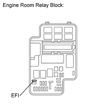
Remove the EFI fuse from the engine room relay block.
-
Measure the resistance according to the value(s) in the table below.
Standard Resistance Tester Connection Condition Specified Condition EFI fuse Always Below 1 Ω -
Reinstall the EFI fuse.
NG
REPLACE FUSE (EFI FUSE)
OK
REPAIR OR REPLACE HARNESS OR CONNECTOR (EFI MAIN RELAY - BATTERY)
-
-
CHECK FUSE (IGN FUSE)
-
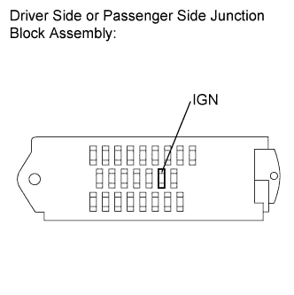
Remove the IGN fuse from the driver side junction block assembly (for RHD) or passenger side junction block assembly (for LHD).
-
Measure the resistance according to the value(s) in the table below.
Standard Resistance Tester Connection Condition Specified Condition IGN fuse Always Below 1 Ω -
Reinstall the IGN fuse.
NG
REPLACE FUSE (IGN FUSE)
OK
-
-
INSPECT RELAY (IG2 RELAY)
-
Remove the IG2 relay from the engine room relay block.
-
Measure the resistance according to the value(s) in the table below.
Standard Resistance Tester Connection Condition Specified Condition 3 - 5 No battery voltage applied to terminals 1 and 2 10 kΩ or higher 3 - 5 Battery voltage applied to terminals 1 and 2 Below 1 Ω -
Reinstall the IG2 relay.
NG
REPLACE RELAY (IG2 RELAY)
OK
-
-
CHECK HARNESS AND CONNECTOR (ECM - IG2 RELAY)
-
Remove the IG2 relay from the engine room relay block.
-
Disconnect the ECM connector.
-
Measure the resistance according to the value(s) in the table below.
Standard Resistance (Check for Open) Tester Connection Condition Specified Condition 3 (IG2 relay) - A8-28 (IGSW) Always Below 1 Ω Standard Resistance (Check for Short) Tester Connection Condition Specified Condition 3 (IG2 relay) or A8-28 (IGSW) - Body ground Always 10 kΩ or higher -
Reinstall the IG2 relay.
-
Reconnect the ECM connector.
NG
REPAIR OR REPLACE HARNESS OR CONNECTOR (ECM - IG2 RELAY)
OK
-
-
CHECK FUSE (IG2 FUSE)
-
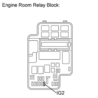
Remove the IG2 fuse from the engine room relay block.
-
Measure the resistance according to the value(s) in the table below.
Standard Resistance Tester Connection Condition Specified Condition IG2 fuse Always Below 1 Ω -
Reinstall the IG2 fuse.
NG
REPLACE FUSE (IG2 FUSE)
OK
-
-
CHECK HARNESS AND CONNECTOR (IG2 RELAY POWER SOURCE CIRCUIT)
-
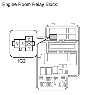
Remove the IG2 relay from the engine room relay block.
-
Measure the voltage according to the value(s) in the table below.
Standard Voltage Tester Connection Condition Specified Condition 5 (IG2 relay) - Body ground Always 11 to 14 V -
Reinstall the IG2 relay.
NG
REPAIR OR REPLACE HARNESS OR CONNECTOR (IG2 RELAY - BATTERY)
OK
GO TO SMART ENTRY AND START SYSTEM Click here
-