DESCRIPTION
The Transmission Control Module (TCM) and ECM perform 2-way communications with each other via the Controller Area Network (CAN). The TCM sends signals to the ECM concerning required engine rpm, required engine torque, warning indicators in the combination meter, DTCs and other data. The ECM sends signals to the TCM concerning engine rpm, opening angles of the throttle valve, temperature of intake air, temperature of engine coolant, engine torques and other data. If the TCM cannot communicate with the ECM, the TCM will conclude that there is a malfunction in the CAN system, illuminate the MIL and set a DTC.
| DTC No. | DTC Detection Condition | Trouble Area |
|---|---|---|
| U0101 |
|
|
INSPECTION PROCEDURE
PROCEDURE
- Click here
CHECK OTHER DTC OUTPUT (IN ADDITION TO DTC U0101)
-
Connect the intelligent tester to the DLC3.
-
Turn the engine switch on (IG).
-
Turn the tester on.
-
Enter the following menus: Powertrain / Engine / DTC.
-
Read the DTCs.
Result Result Proceed to DTC U0101 is output A DTC U0101 and other DTCs are output B Tip:If any DTCs other than U0101 are output, troubleshoot those DTCs first.
-
- Click here
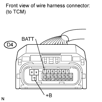
INSPECT ECU POWER SOURCE CIRCUIT (TCM POWER SOURCE)
-
Disconnect the TCM connector.
-
Turn the engine switch on (IG).
-
Measure the resistance according to the value(s) in the table below.
Standard Voltage Tester Connection Switch Condition Specified Condition D4-1 (BATT) - Body ground Always 11 to 14 V D4-18 (+B) - Body ground Engine switch on (IG) 11 to 14 V -
Reconnect the TCM connector.
- OKClick here
- NGClick here
-
- Click here
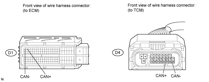
CHECK HARNESS AND CONNECTOR (ECM - TCM)
-
Disconnect the TCM connector.
-
Disconnect the ECM connector.
-
Measure the resistance according to the value(s) in the table below.
Standard Resistance (Check for Open) Tester Connection Condition Specified Condition D4-6 (CAN+) - D1-2 (CAN+) Always Below 1 Ω D4-7 (CAN-) - D1-1 (CAN-) Always Below 1 Ω Standard Resistance (Check for Short) Tester Connection Condition Specified Condition D4-6 (CAN+) or D1-2 (CAN+) - Body ground Always 10 kΩ or higher D4-7 (CAN-) or D1-1 (CAN-) - Body ground Always 10 kΩ or higher -
Reconnect the ECM connector.
-
Reconnect the TCM connector.
- OKClick here
- NGClick here
-
- Click here
REPLACE ECM
-
Replace the ECM (Click here).
- NEXTClick here
-
- Click here
CHECK WHETHER DTC OUTPUT RECURS (DTC U0101)
-
Connect the intelligent tester to the DLC3.
-
Turn the engine switch on (IG) and turn the tester on.
-
Enter the following menus: Powertrain / Engine / DTC.
-
Read the DTCs.
Result Result Proceed to DTC is not output A DTC U0101 is output B
-
- Click here
GO TO DTC CHARTClick here
- Click here
GO TO TCM POWER SOURCE CIRCUITClick here
- Click here
REPAIR OR REPLACE HARNESS OR CONNECTOR (ECM - TCM)
- Click here
END
- Click here
REPLACE TCMClick here