SFI SYSTEM, Diagnostic DTC:P0705

| DTC Code | DTC Name |
|---|---|
| P0705 | Transmission Range Sensor Circuit Malfunction (PRNDL Input) |
DESCRIPTION
The park/neutral position switch assembly detects the shift lever position and sends signals to the ECM.
| DTC No. | DTC Detection Condition | Trouble Area |
|---|---|---|
| P0705 | (A) Any 2 or more of the following signals are on simultaneously (2 trip detection logic):
(B) Any 2 or more of the following signals are on simultaneously (2 trip detection logic):
(C) Any of the following conditions is met for 2.0 sec. or more in the S position (2 trip detection logic):
(D) All switches are off simultaneously for NSW, P, R, N and D. |
|
MONITOR DESCRIPTION
These DTCs indicate a problem with the park/neutral position switch assembly and the wire harness in the park/neutral position switch circuit.
The park/neutral position switch assembly detects the shift lever position and sends a signal to the ECM.
For security, the park/neutral position switch assembly detects the shift lever position so that the engine can be started only when the shift lever is in P or N.
The park/neutral position switch assembly sends a signal to the ECM according to the shift lever position (P, R, N, D, or S). The ECM determines that there is a problem with the switch or related parts if it receives more than 1 position signal simultaneously. The ECM will turn on the MIL and store the DTC.
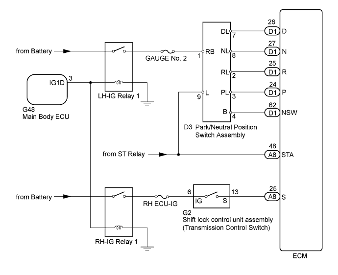
WIRING DIAGRAM
INSPECTION PROCEDURE
-
DATA LIST
Tech Tips
Using the intelligent tester to read the Data List allows the values or states of switches, sensor, actuators and other items to be read without removing any parts. This non-intrusive inspection can be very useful because intermittent conditions or signals may by discovered before parts or wiring is disturbed. Reading the Data List information early in troubleshooting is one way to save diagnostic time.
Note
In the table below, the values listed under "Normal Condition" are reference values. Do not depend solely on these reference values when deciding whether a part is faulty or not.
-
Warm up the engine.
-
Turn the engine switch off.
-
Connect the intelligent tester to the DLC3.
-
Turn the engine switch on (IG).
-
Turn the tester on.
-
Enter the following menus: Powertrain / Engine / Data List / All Data.
-
Read the values displayed on the tester.
Tester Display Measurement Item/Range Normal Condition Diagnostic Note Shift SW Status (R Range) Park/neutral position switch status/
ON or OFF
-
ON: Shift lever in R
-
OFF: Shift lever not in R
When shift lever position displayed on intelligent tester differs from actual position, adjustment of park/neutral position switch assembly or shift cable may be incorrect Shift SW Status (P Range) Park/neutral position switch status/
ON or OFF
-
ON: Shift lever in P
-
OFF: Shift lever not in P
When shift lever position displayed on intelligent tester differs from actual position, adjustment of park/neutral position switch assembly or shift cable may be incorrect Shift SW Status (N Range) Park/neutral position switch status/
ON or OFF
-
ON: Shift lever in N
-
OFF: Shift lever not in N
When shift lever position displayed on intelligent tester differs from actual position, adjustment of park/neutral position switch assembly or shift cable may be incorrect Shift SW Status (D Range) Park/neutral position switch status/
ON or OFF
-
ON: Shift lever in D or S
-
OFF: Shift lever not in D or S
When shift lever position displayed on intelligent tester differs from actual position, adjustment of park/neutral position switch assembly or shift cable may be incorrect Sports Mode Selection SW Sport Mode Select Switch Status/
ON or OFF
-
ON: Shift lever in S, "+" or "-"
-
OFF: Shift lever not in S, "+" and "-"
- -
-
PROCEDURE
-
READ VALUE USING INTELLIGENT TESTER
-
Connect the intelligent tester to the DLC3.
-
Turn the engine switch on (IG).
-
Turn the tester on.
-
Enter the following menus: Powertrain / Engine / Data List / All Data.
-
Read the values displayed on the tester.
OK Tester Display Shift Lever Specified Condition Neutral Position SW Signal P or N ON Except P or N OFF Shift SW Status (R Range) R ON Except R OFF Shift SW Status (P Range) P ON Except P OFF Shift SW Status (N Range) N ON Except N OFF Shift SW Status (D Range) D or S ON Except D or S OFF
NG 
CHECK HARNESS AND CONNECTOR (PARK/NEUTRAL POSITION SWITCH ASSEMBLY VOLTAGE) Click here
OK 
-
-
READ VALUE USING INTELLIGENT TESTER (SPORTS MODE SELECTION SW)
-
Connect the intelligent tester to the DLC3.
-
Turn the engine switch on (IG).
-
Turn the tester on.
-
Enter the following menus: Powertrain / Engine / Data List / Sports Mode Selection SW.
-
Read the values displayed on the tester.
OK Tester Display Shift Lever Specified Condition Sports Mode Selection SW S ON Except S OFF
NG
INSPECT SHIFT LOCK CONTROL UNIT ASSEMBLY Click here
OK 
CHECK FOR INTERMITTENT PROBLEMS Click here
-
-
INSPECT SHIFT LOCK CONTROL UNIT ASSEMBLY
-
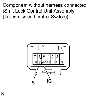
Disconnect the shift lock control unit assembly (transmission control switch) connector.
-
Measure the resistance according to the value(s) in the table below.
Standard Resistance Tester Connection Condition Specified Condition 6 (IG) - 13 (S) Shift lever in S, "+" or "-" Below 1 Ω Shift lever in any position other than S, "+" and "-" 10 kΩ or higher -
Reconnect the shift lock control unit assembly (transmission control switch) connector.
NG 
REPLACE SHIFT LOCK CONTROL UNIT ASSEMBLY Click here
OK
REPAIR OR REPLACE HARNESS OR CONNECTOR (ECM - TRANSMISSION CONTROL SWITCH)
-
-
CHECK HARNESS AND CONNECTOR (PARK/NEUTRAL POSITION SWITCH ASSEMBLY VOLTAGE)
-
Disconnect the park/neutral position switch assembly connector.
-
Turn the engine switch on (IG).
-
Measure the voltage according to the value(s) in the table below.
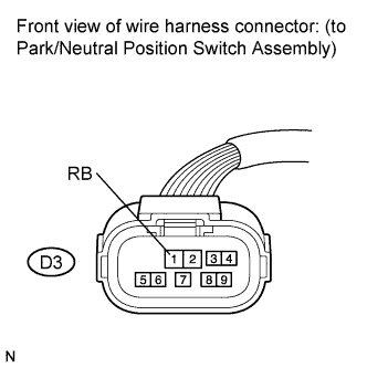
Standard Voltage Tester Connection Switch Condition Specified Condition D3-1 (RB) - Body ground Engine switch on (IG) 11 to 14 V -
Reconnect the park/neutral position switch assembly connector.
NG
CHECK FUSE (GAUGE NO. 2 FUSE) Click here
OK
-
-
INSPECT PARK/NEUTRAL POSITION SWITCH ASSEMBLY
-
Disconnect the park/neutral position switch assembly connector.
-
Measure the resistance according to the value(s) in the table below.
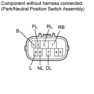
Standard Resistance Tester Connection Condition Specified Condition 1 (RB) - 3 (PL)
4 (B) - 9 (L)
Shift lever in P Below 1 Ω Shift lever in any position other than P 10 kΩ or higher 2 (RL) - 1 (RB) Shift lever in R Below 1 Ω Shift lever in any position other than R 10 kΩ or higher 1 (RB) - 8 (NL)
4 (B) - 9 (L)
Shift lever in N Below 1 Ω Shift lever in any position other than N 10 kΩ or higher 1 (RB) - 7 (DL) Shift lever in D or S Below 1 Ω Shift lever in any position other than D and S 10 kΩ or higher -
Reconnect the park/neutral position switch assembly connector.
NG
REPLACE PARK/NEUTRAL POSITION SWITCH ASSEMBLY Click here
OK
-
-
CHECK HARNESS AND CONNECTOR (ECM - PARK/NEUTRAL POSITION SWITCH ASSEMBLY)
-
Disconnect the ECM connector.
-
Turn the engine switch on (IG).
-
Measure the voltage according to the value(s) in the table below.
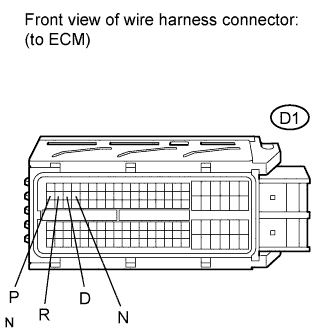
Standard Voltage Tester Connection Condition Specified Condition D1-24 (P) - Body ground
-
Engine switch on (IG)
-
Shift lever in P
11 to 14 V
-
Engine switch on (IG)
-
Shift lever in any position other than P
0 to 1.5 V D1-25 (R) - Body ground
-
Engine switch on (IG)
-
Shift lever in R
11 to 14 V
-
Engine switch on (IG)
-
Shift lever in any position other than R
0 to 1.5 V D1-27 (N) - Body ground
-
Engine switch on (IG)
-
Shift lever in N
11 to 14 V
-
Engine switch on (IG)
-
Shift lever in any position other than N
0 to 1.5 V D1-26 (D) - Body ground
-
Engine switch on (IG)
-
Shift lever in D
11 to 14 V
-
Engine switch on (IG)
-
Shift lever in any position other than D
0 to 1.5 V -
-
Reconnect the ECM connector.
NG
REPAIR OR REPLACE HARNESS OR CONNECTOR (ECM - PARK/NEUTRAL POSITION SWITCH ASSEMBLY)
OK
-
-
CHECK HARNESS AND CONNECTOR (PARK/NEUTRAL POSITION SWITCH ASSEMBLY - ECM)
-
Disconnect the park/neutral position switch assembly connector.
-
Disconnect the ECM connector.
-
Measure the resistance according to the value(s) in the table below.
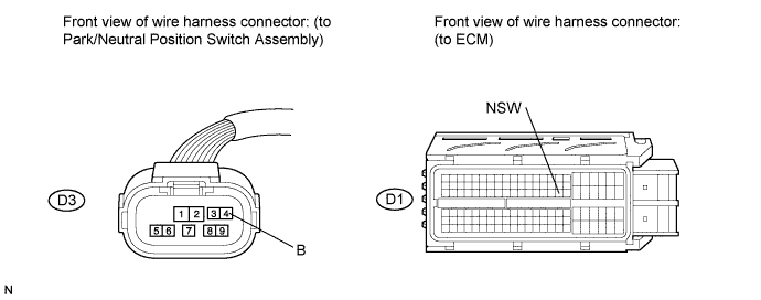
Standard Resistance (Check for Open) Tester Connection Condition Specified Condition D3-4 (B) - D1-62 (NSW) Always Below 1 Ω Standard Resistance (Check for Short) Tester Connection Condition Specified Condition D3-4 (B) or D1-62 (NSW) - Body ground Always 10 kΩ or higher -
Reconnect the ECM connector.
-
Reconnect the park/neutral position switch assembly connector.
NG
REPAIR OR REPLACE HARNESS OR CONNECTOR (PARK/NEUTRAL POSITION SWITCH ASSEMBLY - ECM)
OK
REPLACE ECM Click here
-
-
CHECK FUSE (GAUGE NO. 2 FUSE)
-
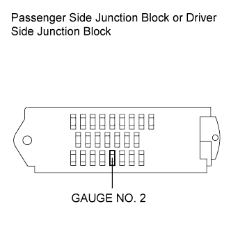
Remove the GAUGE NO. 2 fuse from the passenger side junction block (for RHD) or driver side junction block (for LHD).
-
Measure the resistance according to the value(s) in the table below.
Standard Resistance Tester Connection Condition Specified Condition GAUGE NO. 2 fuse Always Below 1 Ω -
Reinstall the GAUGE NO. 2 fuse.
NG
REPLACE FUSE (GAUGE NO. 2 FUSE)
OK
-
-
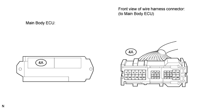
CHECK MAIN BODY ECU (LH-IG RELAY 1 RELAY)
-
Disconnect the main body ECU connector.
-
Measure the resistance according to the value(s) in the table below.
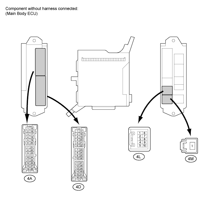
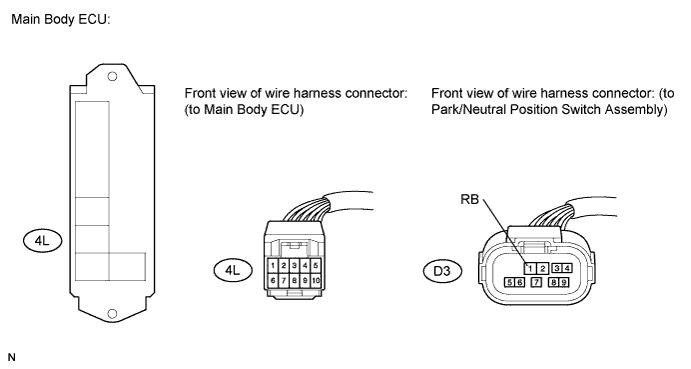
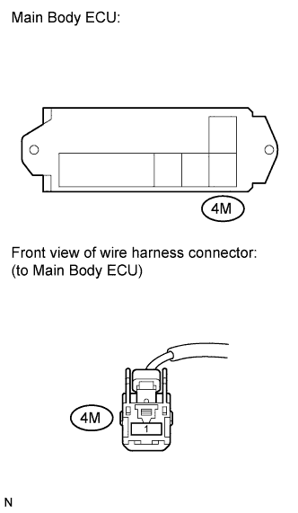
Standard Resistance Tester Connection Condition Specified Condition 4L-9 - 4M-1 No battery voltage applied to terminals 4D-11 and 4A-5 10 kΩ or higher 4L-9 - 4M-1 Battery voltage applied to terminals 4D-11 and 4A-5 Below 1 Ω -
Reconnect the main body ECU connector.
NG
REPLACE MAIN BODY ECU
OK
-
-
CHECK HARNESS AND CONNECTOR (MAIN BODY ECU - BODY GROUND)
-
Disconnect the main body ECU connector.
-
Measure the resistance according to the value(s) in the table below.
Standard Resistance (Check for Open) Tester Connection Condition Specified Condition 4A-5 - Body ground Always Below 1 Ω -
Reconnect the main body ECU connector.
NG
REPAIR OR REPLACE HARNESS OR CONNECTOR (MAIN BODY ECU - BODY GROUND)
OK
-
-
CHECK HARNESS AND CONNECTOR (PARK/NEUTRAL POSITION SWITCH - MAIN BODY ECU)
-
Disconnect the park/neutral position switch assembly connector.
-
Disconnect the main body ECU connector.
-
Measure the resistance according to the value(s) in the table below.
Standard Resistance (Check for Open) Tester Connection Condition Specified Condition D3-1 (RB) - 4L-9 Always Below 1 Ω Standard Resistance (Check for Short) Tester Connection Condition Specified Condition D3-1 (RB) or 4L-9 - Body ground Always 10 kΩ or higher -
Reconnect the main body ECU connector.
-
Reconnect the park/neutral position switch assembly connector.
NG
REPAIR OR REPLACE HARNESS OR CONNECTOR (PARK/NEUTRAL POSITION SWITCH - MAIN BODY ECU)
OK
-
-
INSPECT MAIN BODY ECU (4M-1 VOLTAGE)
-
Reconnect the main body ECU connector.
-
Measure the voltage according to the value(s) in the table below.
Standard Voltage Tester Connection Condition Specified Condition 4M-1 - Body ground Always 11 to 14 V -
Reconnect the main body ECU connector.
NG
REPAIR OR REPLACE HARNESS OR CONNECTOR (MAIN BODY ECU - BODY GROUND)
OK
REPLACE MAIN BODY ECU
-