DESCRIPTION
The stop light switch assembly is a duplex system that transmits 2 signals: STP and ST1-. These 2 signals are used by the ECM to monitor whether or not the brake system is working properly.
The purpose of this circuit is to prevent the engine from stalling while driving with the lock-up torque converter clutch on when the brakes are suddenly applied.
When the brake pedal is depressed, this switch sends a signal to the ECM. Then the ECM cancels the operation of the lock-up clutch while braking is in progress.
| DTC No. | DTC Detection Condition | Trouble Area |
|---|---|---|
| P0724 | Stop light switch remains on even when vehicle is driven in GO (30 km/h (18.63 mph) or more) and STOP (less than 3 km/h (1.86 mph)) pattern 5 times (2 trip detection logic) |
|
INSPECTION PROCEDURE
-
Using the intelligent tester to read the Data List allows the values or states of switches, sensors, actuators and other items to be read without removing any parts. Reading the Data List information early in troubleshooting is one way to save diagnostic time.
-
Read freeze frame data using the intelligent tester. The ECM records vehicle and driving condition information as freeze frame data the moment a DTC is stored. When troubleshooting, freeze frame data can be helpful in determining whether the vehicle was running or stopped, whether the engine was warmed up or not, whether the air fuel ratio was lean or rich, as well as other data recorded at the time of a malfunction.
PROCEDURE
- Click here
READ VALUE USING INTELLIGENT TESTER (STOP LIGHT SWITCH)
-
Connect the intelligent tester to the DLC3.
-
Turn the engine switch on (IG).
-
Turn the tester on.
-
Enter the following menus: Powertrain / Engine / Data List / Stop Light Switch.
-
Read the value displayed on the tester when the brake pedal is depressed and released.
OK Brake Pedal Display Released OFF Depressed ON
- OKClick here
- NGClick here
-
- Click here
INSPECT STOP LIGHT SWITCH ASSEMBLY
-
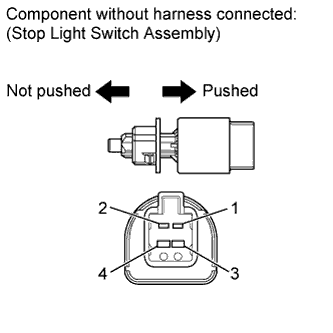
Disconnect the stop light switch assembly connector.
-
Remove the stop light switch assembly.
-
Measure the resistance according to the value(s) in the table below.
Standard Resistance Tester Connection Switch Position Specified Condition 1 - 2 Switch pin not pushed Below 1 Ω Switch pin pushed 10 kΩ or higher 3 - 4 Switch pin not pushed 10 kΩ or higher Switch pin pushed Below 1 Ω -
Reinstall the stop light switch assembly.
-
Reconnect the stop light switch assembly connector.
- OKClick here
- NGClick here
-
- Click here
CHECK HARNESS AND CONNECTOR (ECM - STOP LIGHT SWITCH ASSEMBLY)
-
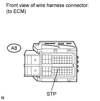
Disconnect the ECM connector.
-
Measure the voltage according to the value(s) in the table below.
Standard Voltage Tester Connection Condition Specified Condition A8-36 (STP) - Body ground Brake pedal depressed 7.5 to 14 V A8-36 (STP) - Body ground Brake pedal released 0 to 1.5 V -
Reconnect the ECM connector.
- OKClick here
- NGClick here
-
- Click here
CHECK FOR INTERMITTENT PROBLEMSClick here
- Click here
REPLACE STOP LIGHT SWITCH ASSEMBLYClick here
- Click here
REPLACE ECMClick here
- Click here
REPAIR OR REPLACE HARNESS OR CONNECTOR (ECM - STOP LIGHT SWITCH ASSEMBLY)