SFI SYSTEM, Diagnostic DTC:P0660

| DTC Code | DTC Name |
|---|---|
| P0660 | Intake Manifold Tuning Valve Control Circuit / Open (Bank 1) |
DESCRIPTION
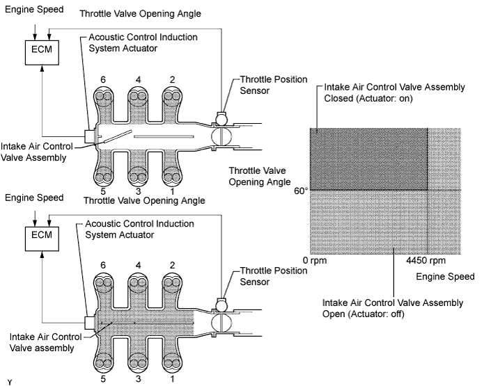
This circuit opens and closes the intake air control valve assembly in response to changes in the engine load in order to increase the intake efficiency using the acoustic control induction system.
When the engine speed is between 0 and 4450 rpm and the throttle valve opening angle is 60°C or more, the ECM supplies current to the actuator (on status), to close the intake air control valve assembly. Under other conditions, the VSV is usually off and the intake air control valve is open.
| DTC No. | DTC Detection Condition | Trouble Area |
|---|---|---|
| P0660 | The following conditions are met simultaneously for 0.5 seconds or more (2 trip detection logic):
|
|
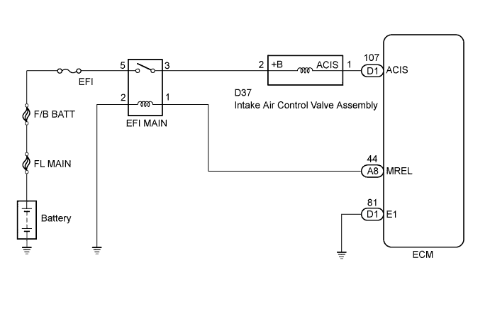
WIRING DIAGRAM
INSPECTION PROCEDURE
PROCEDURE
-
PERFORM ACTIVE TEST USING INTELLIGENT TESTER
-
Connect the intelligent tester to the DLC3.
-
Turn the engine switch on (IG) and turn the intelligent tester on.
-
Enter the following menus: Powertrain / Engine / Active Test / Activate the VSV for Intake Control.
-
Check if operating noise can be heard when operating the intake control valve using the intelligent tester.
OK Operating noise can be heard.
NG 
CHECK INTAKE AIR SURGE TANK ASSEMBLY (INTAKE AIR CONTROL VALVE ASSEMBLY OPERATION) Click here
OK 
CHECK FOR INTERMITTENT PROBLEMS Click here
-
-
CHECK INTAKE AIR SURGE TANK ASSEMBLY (INTAKE AIR CONTROL VALVE ASSEMBLY OPERATION)
-
Disconnect the intake air control valve assembly connector.
-
Apply battery voltage between the terminals of the intake air control valve assembly connector.
-
Check the intake air control valve assembly operation.
OK Operating noise can be heard. -
Reconnect the intake air control valve assembly connector.
NG 
REPLACE INTAKE AIR SURGE TANK ASSEMBLY Click here
OK 
-
-
CHECK HARNESS AND CONNECTOR (INTAKE AIR CONTROL VALVE ASSEMBLY VOLTAGE)
-
Disconnect the intake air control valve assembly connector.
-
Turn the engine switch on (IG).
-
Measure the voltage according to the value(s) in the table below.
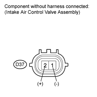
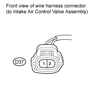
Standard Voltage Tester Connection Switch Condition Specified Condition D37-2 (+B) - Body ground Engine switch on (IG) 11 to 14 V -
Reconnect the intake air control valve assembly connector.
NG
REPAIR OR REPLACE HARNESS OR CONNECTOR (EFI MAIN RELAY - INTAKE AIR CONTROL VALVE ASSEMBLY)
OK
-
-
CHECK HARNESS AND CONNECTOR (INTAKE AIR CONTROL VALVE ASSEMBLY - ECM)
-
Disconnect the intake air control valve assembly connector.
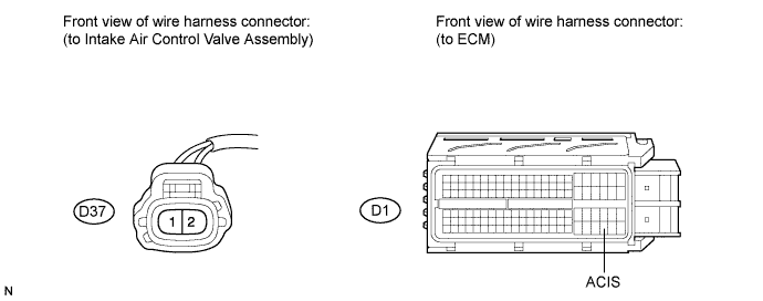
-
Disconnect the ECM connector.
-
Measure the resistance according to the value(s) in the table below.
Standard Resistance (Check for Open) Tester Connection Condition Specified Condition D37-1 (ACIS) - D1-107 (ACIS) Always Below 1 Ω Standard Resistance (Check for Short) Tester Connection Condition Specified Condition D37-1 (ACIS) or D1-107 (ACIS) - D1-1 (E1) Always 10 kΩ or higher -
Reconnect the intake air control valve assembly connector.
-
Reconnect the ECM connector.
NG
REPAIR OR REPLACE HARNESS OR CONNECTOR (INTAKE AIR CONTROL VALVE ASSEMBLY - ECM)
OK
REPLACE ECM Click here
-