DESCRIPTION
The cranking holding control system keeps energizing the ST relay after the ECM detects the starter signal (STSW signal) from the main body ECU until the ECM confirms that the engine has started. Furthermore, the ECM outputs an accessory cut signal (ACCR signal) to the ACC relay during cranking to prevent flickering of the combination meter, clock, audio system, and so on.
When the ECM detects the STSW signal, the ECM outputs the starter relay drive signal (STAR signal) to the starter relay through the park/neutral position switch assembly, and then, the engine is cranked. When the ECM receives a stable engine speed signal (NE signal), more specifically, when the NE signal reaches a predetermined value, the ECM stops outputting the STAR signal. Also, the ECM monitors the ST relay operating conditions based on the STA terminal voltage status.
| DTC No. | DTC Detection Condition | Trouble Area |
|---|---|---|
| P0617 | When conditions (a), (b) and (c) are met, positive (+B) battery voltage 10.5 V or more is applied to ECM for 20 seconds (1 trip detection logic):
|
|
INSPECTION PROCEDURE
-
The following troubleshooting procedure is based on the premise that the engine is cranked normally.
If the engine does not crank, proceed to the Problem Symptoms Table (Click here).
-
Read freeze frame data using the intelligent tester. The ECM records vehicle and driving condition information as freeze frame data the moment a DTC is stored. When troubleshooting, freeze frame data can be helpful in determining whether the vehicle was running or stopped, whether the engine was warmed up or not, whether the air fuel ratio was lean or rich, as well as other data recorded at the time of a malfunction.
PROCEDURE
- Click here
READ VALUE USING INTELLIGENT TESTER (STARTER SIGNAL)
-
Connect the intelligent tester to the DLC3.
-
Turn the engine switch on (IG) and turn the tester on.
-
Enter the following menus: Powertrain / Engine / Data List / Starter Signal.
-
Read the value displayed on the tester when the engine switch is on (IG) and the engine is started.
OK Condition Tester Display Engine switch on (IG) OFF Engine started ON
- OKClick here
- NGClick here
-
- Click here
INSPECT PARK/NEUTRAL POSITION SWITCH ASSEMBLY
-
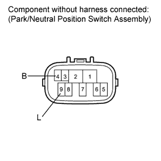
Inspect the park/neutral position switch assembly.
-
Disconnect the park/neutral position switch assembly connector.
-
Measure the resistance according to the value(s) in the table below.
Standard Resistance Tester Connection Condition Specified Condition 4 (B) - 9 (L) Shift lever in P or N Below 1 Ω 4 (B) - 9 (L) Shift lever in any position other than P or N 10 kΩ or higher -
Reconnect the park/neutral position switch assembly connector.
-
- OKClick here
- NGClick here
-
- Click here
CHECK FOR INTERMITTENT PROBLEMSClick here
- Click here
REPLACE PARK/NEUTRAL POSITION SWITCH ASSEMBLYClick here
- Click here
CHECK CRANKING HOLDING FUNCTION CIRCUITClick here