SFI SYSTEM, Diagnostic DTC:P0500

| DTC Code | DTC Name |
|---|---|
| P0500 | Vehicle Speed Sensor "A" |
DESCRIPTION
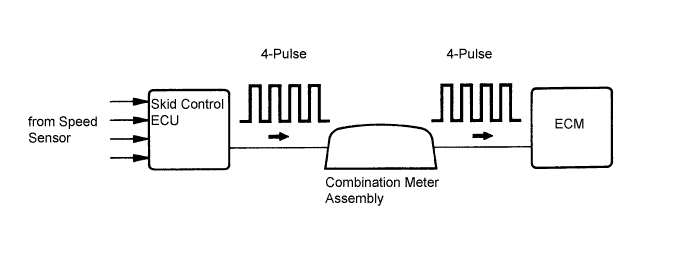
The wheel speed sensors monitor the wheel rotation speed and send signals to the skid control ECU. The skid control ECU converts the wheel speed signal into a 4-pulse signal and transmits it to the ECM via the combination meter assembly. The ECM determines the vehicle speed based on the frequency of the pulse signal.
Tech Tips
-
A voltage of 12 V or 5 V is output from each ECU and then input to the combination meter assembly. The signal is changed to a pulse signal at the transistor in the combination meter assembly. Each ECU controls the respective system based on the pulse signal.
-
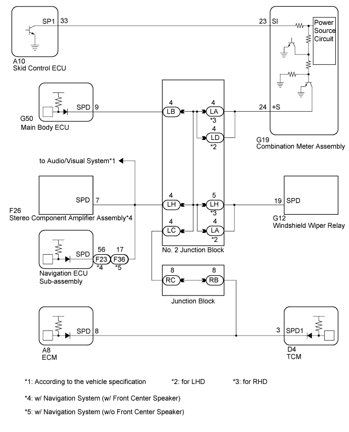
If a short occurs in any of the ECUs or in the wire harness connected to an ECU, all systems in the wiring diagram below will not operate normally.
| DTC No. | DTC Detection Condition | Trouble Area |
|---|---|---|
| P0500 | Either of the following conditions (A) and (B) are met (1 trip detection logic) (A) Either of the following conditions 1or 2 is met
(B) While vehicle is being driven, no vehicle speed sensor signal is sent ECM |
|
WIRING DIAGRAM
INSPECTION PROCEDURE
Tech Tips
Read freeze frame data using the intelligent tester. The ECM records vehicle and driving condition information as freeze frame data the moment a DTC is stored. When troubleshooting, freeze frame data can be helpful in determining whether the vehicle was running or stopped, whether the engine was warmed up or not, whether the air fuel ratio was lean or rich, as well as other data recorded at the time of a malfunction.
PROCEDURE
-
READ VALUE USING INTELLIGENT TESTER (VEHICLE SPEED)
-
Drive the vehicle and check whether the operation of the speedometer in the combination meter assembly is normal.
Tech Tips
-
The vehicle speed sensor is operating normally if the speedometer reading is normal.
-
If the speedometer does not operate, check it by following the procedure described for a speedometer malfunction.
-
-
Connect the intelligent tester to the DLC3.
-
Turn the engine switch on (IG).
-
Turn the tester on.
-
Enter the following menus: Powertrain / Engine / Data List / Vehicle Speed.
-
Drive the vehicle.
-
Read the value displayed on the tester.
OK Vehicle speeds displayed on tester and speedometer display are equal.
NG 
CHECK COMBINATION METER ASSEMBLY (SPD SIGNAL WAVEFORM) Click here
OK 
CHECK FOR INTERMITTENT PROBLEMS Click here
-
-
CHECK COMBINATION METER ASSEMBLY (SPD SIGNAL WAVEFORM)
-
Inspect the combination meter assembly using an oscilloscope.
-
Move the shift lever to N.
-
Jack up the vehicle.
-
Turn the engine switch on (IG).
-
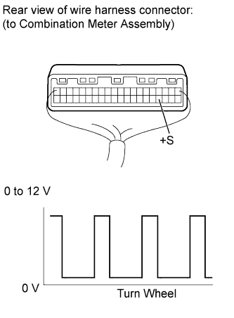
Measure the voltage between the terminal of the combination meter assembly and the body ground while the wheel is turned slowly.
Standard Voltage Tester Connection Switch Condition Specified Condition G19-24 (+S) - Body ground Engine switch on (IG) Voltage generated intermittently Tech Tips
The output voltage should fluctuate up and down, similarly to the diagram, when the wheel is turned slowly.
-
NG 
GO TO METER / GAUGE SYSTEM (SPEED SIGNAL CIRCUIT) Click here
OK 
-
-
CHECK HARNESS AND CONNECTOR (COMBINATION METER ASSEMBLY - ECM)
-
Disconnect the combination meter assembly connector.
-
Disconnect the ECM connector.
-
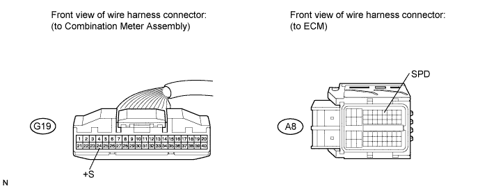
Measure the resistance according to the value(s) in the table below.
Standard Resistance (Check for Open) Tester Connection Condition Specified Condition G19-24 (+S) - A8-8 (SPD) Always Below 1 Ω -
Reconnect the combination meter assembly connector.
-
Reconnect the ECM connector.
NG
REPAIR OR REPLACE HARNESS OR CONNECTOR (COMBINATION METER ASSEMBLY - ECM)
OK
REPLACE ECM Click here
-