SFI SYSTEM, Diagnostic DTC:P0617

| DTC Code | DTC Name |
|---|---|
| P0617 | Starter Relay Circuit High |
DESCRIPTION
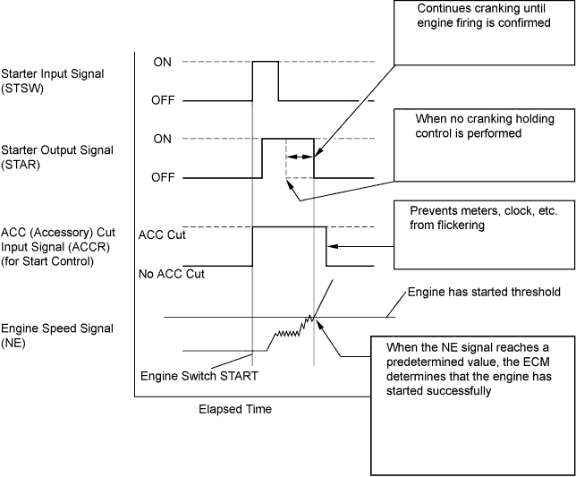
The cranking holding control system keeps energizing the ST relay after the ECM detects the starter signal (STSW signal) from the main body ECU until the ECM confirms that the engine has started. Furthermore, the ECM outputs an accessory cut signal (ACCR signal) to the ACC relay during cranking to prevent flickering of the combination meter, clock, audio system, and so on.
When the ECM detects the STSW signal, the ECM outputs the starter relay drive signal (STAR signal) to the starter relay through the park/neutral position switch assembly, and then, the engine is cranked. When the ECM receives a stable engine speed signal (NE signal), more specifically, when the NE signal reaches a predetermined value, the ECM stops outputting the STAR signal. Also, the ECM monitors the ST relay operating conditions based on the STA terminal voltage status.
While the engine is being cranked, battery voltage is applied to terminal STA of the ECM. If the ECM detects the starter signal (STA signal) while the vehicle is being driven, it determines that there is a malfunction in the STA circuit. The ECM then illuminates the MIL and sets the DTC.
This monitor runs when the vehicle is driven at 20 km/h (12 mph) or more for over 20 seconds.
| DTC No. | DTC Detection Condition | Trouble Area |
|---|---|---|
| P0617 | When conditions (a), (b) and (c) are met, positive (+B) battery voltage 10.5 V or more is applied to ECM for 20 seconds (1 trip detection logic):
|
|
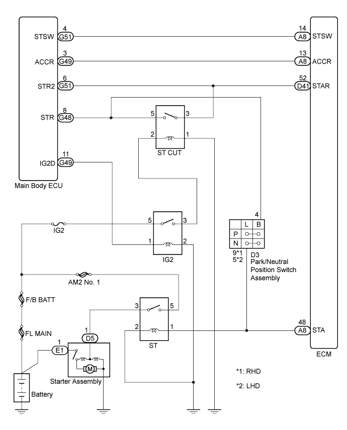
WIRING DIAGRAM
INSPECTION PROCEDURE
Tech Tips
Read freeze frame data using the intelligent tester. The ECM records vehicle and driving condition information as freeze frame data the moment a DTC is stored. When troubleshooting, freeze frame data can help determine if the vehicle was moving or stationary, if the engine was warmed up or not, if the air fuel ratio was lean or rich, and other data from the time the malfunction occurred
PROCEDURE
-
READ VALUE USING INTELLIGENT TESTER (STARTER SIGNAL)
-
Connect the intelligent tester to the DLC3.
-
Turn the engine switch on (IG) and turn the tester on.
-
Enter the following menus: Powertrain / Engine and ECT / Data List / Starter Signal.
-
Check the value displayed on the tester when the vehicle is driven at 20 km/h (12 mph) or more.
Result Condition Tester Display Result Driving at 20 km/h (12 mph) or more OFF*1
Close*2
A ON*1
Open*2
B
-
*1: for models w/ CVT (w/o Euro-OBD)
-
*2: for other models
-
B 
INSPECT PARK/NEUTRAL POSITION SWITCH ASSEMBLY Click here
A 
CHECK FOR INTERMITTENT PROBLEMS Click here
-
-
INSPECT PARK/NEUTRAL POSITION SWITCH ASSEMBLY
-
Inspect the park/neutral position switch assembly for A/T models Click here or CVT models Click here.
Result Result Proceed to OK A NG (for A/T models) B NG (for CVT models) C
B 
REPLACE PARK/NEUTRAL POSITION SWITCH ASSEMBLY Click here
C
REPLACE PARK/NEUTRAL POSITION SWITCH ASSEMBLY Click here
A
CHECK CRANKING HOLDING FUNCTION CIRCUIT Click here
-