Click here
-
PROCEDURES NECESSARY WHEN BATTERY TERMINAL IS DISCONNECTED/RECONNECTED
Necessary Procedures Procedure Details Effects / Inoperative Functions When Necessary Procedures are not Performed Notes Correct the steering angle neutral point Fully turn the steering wheel to the right and left on the flat ground. Parking assist monitor system When "System initializing" message is displayed on the navigation display, perform this procedure. Reset back door close position Fully close the back door to turn off the courtesy switch.
-
Power back door function
-
Back door closer function
-
If the back door is closed when disconnecting the cable from the battery terminal, it is not necessary to reset it.
-
The power back door ECU controls the locked or unlocked state of the back door based on its memory. If the power for the power back door ECU is disconnected and reconnected, the back door will need to be unlocked before it can be operated.
Reset slide door close position Fully close the slide door to turn off the courtesy switch.
-
Power slide door function
-
Slide door closer function
If the slide door is closed when disconnecting the cable from the battery terminal, it is not necessary to reset it. Note:After the engine switch is turned off, the navigation receiver assembly records various types of memory and settings. As a result, after turning the engine switch off, make sure to wait at least 60 seconds before disconnecting the cable from the negative (-) battery terminal.
-
-
PROCEDURES NECESSARY WHEN ECU OR OTHER PARTS ARE REPLACED
Replacement Part Necessary Procedure Effect / Inoperative Function when Necessary Procedures are not Performed Note ECM ECU communication ID registration Engine start See the Service Bulletin for the registration method.
-
ECM*1
-
Automatic transaxle assembly*1
-
Engine assembly*1
Reset memory
-
Large shift shock
-
The deterioration of fuel efficiency
Use the Intelligent tester. Automatic transaxle assembly*2
-
Reset memory
-
Transaxle Compensation Code Input
-
Perform road test to allow TCM to Learn
-
Large shift shock
-
The deterioration of fuel efficiency
Use the Intelligent tester.
-
Valve Body Assembly*2
-
Shift Solenoid Valve SL3 and/or SL4*2
-
Reset memory
-
Reset transaxle Compensation Code
-
Perform road test to allow TCM to Learn
-
Large shift shock
-
The deterioration of fuel efficiency
Use the Intelligent tester. Shift Solenoid Valve SL1 and/or SL2*2 Perform road test to allow TCM to Learn
-
Large shift shock
-
The deterioration of fuel efficiency
- TCM (If possible, read the transaxle compensation code from the previous TCM)*2 Possible
-
Reset memory
-
Transaxle Compensation Code Input (Into the new TCM)
-
Perform road test to allow TCM to Learn
-
Large shift shock
-
The deterioration of fuel efficiency
Use the Intelligent tester. Impossible
-
Reset memory
-
Reset transaxle Compensation Code
-
Perform road test to allow TCM to Learn
-
Large shift shock
-
The deterioration of fuel efficiency
Use the Intelligent tester.
-
ECM*3
-
Continuously variable transaxle assembly*3
-
Oil pressure sensor*3
-
Yaw rate and acceleration sensor*3
-
Reset memory
-
Deceleration sensor 0 point Calibration
-
CVT oil pressure calibration
-
DTCs are output
-
Neutral control is prohibited
-
Deterioration of fuel efficiency
Perform deceleration sensor 0 point calibration with the engine switch on (engine stopped). Brake actuator assembly (Skid control ECU) Engine variant learning VSC function - Power steering ECU Rotation angle sensor initialization and torque sensor zero point calibration
-
P/S warning light comes on
-
EPS control
DTC (C1515/C1525) will be stored when the power steering ECU is replaced. Steering column assembly Rotation angle sensor initialization and torque sensor zero point calibration Steering effort is different between turning steering wheel to left and right - Navigation ECU sub-assembly*4 Vehicle contract setting G-BOOK service - Hard disk drive*4 Download necessary data Some G-BOOK service content will be unavailable. -
-
Spiral cable sub-assembly
-
Steering sensor
Steering angle setting Parking assist monitor system - Navigation ECU sub-assembly Parking assist ECU initialization Parking assist monitor system -
-
Rear television camera assembly
-
Suspension, tires, etc.
Rear television camera optical axis (Camera position setting) Parking assist monitor system Necessary when vehicle height changes due to replacement of the suspension or tire, etc. Steering lock actuator (Steering lock ECU) ECU code registration Engine start See the Service Bulletin for the registration method.
-
Certification ECU
-
Electrical key transmitter
Key ID registration
-
Wireless door lock control system
-
Smart entry and start system
See the Service Bulletin for the registration method. ID code box
-
ECU code registration
-
ECU communication ID registration
-
Wireless door lock control system
-
Smart entry and start system (for Start Function)
See the Service Bulletin for the registration method. Position control ECU assembly*5
-
Clear the seat position memory
-
Register the seat position
Rear power seat control system (w/ Memory) Necessary when the rear No. 1 seat assembly is disassembly and reassembly. Rear height control sensor sub-assembly LH Perform AFS ECU or headlight leveling ECU initialization Headlight leveling function
-
Necessary when the sensor is removed and installed
-
Necessary when vehicle height changes due to replacement of the suspension
-
Adjust the headlight aim after initializing the AFS ECU or headlight leveling ECU
AFS ECU or headlight leveling ECU Perform AFS ECU or headlight leveling ECU initialization
-
AFS function
-
Headlight leveling function
-
-
Power window regulator motor
-
Door window regulator
Initialize power window control system
-
Automatic door glass open/ close function
-
Jam protection function
-
Operation function after engine switch is turned off
-
Remote control function
Necessary when the regulator is removed and installed. Sliding roof ECU (sliding roof drive gear assembly) Initializing sliding roof ECU (sliding roof drive gear assembly)
-
Automatic open/close function of roof glass
-
Jam protection function
Necessary when the sliding roof ECU is removed and installed (not necessary when the sliding roof ECU (sliding roof drive gear assembly) is removed and installed together with the sliding roof housing).
-
*1: for U241E Automatic Transaxle
-
*2: for U660E Automatic Transaxle
-
*3: w/ Continuously Variable Transaxle System
-
*4: w/ G-BOOK System
-
*5: w/ Seat Position Memory System
-
-
RESET MEMORY (U241E Automatic Transaxle System)
Note:
-
Perform RESET MEMORY (AT initialization) when replacing the automatic transaxle assembly, engine assembly or ECM.
-
RESET MEMORY can be performed only with the Intelligent tester.
Tip:The ECM learns various conditions and controls the automatic transaxle assembly and engine assembly according to those characteristics. Therefore, when the automatic transaxle assembly, engine assembly, or ECM has been replaced, it is necessary to reset the memory so that the ECM can re-learn.
Reset procedure is as follows.
-
Turn the engine switch off.
-
Connect the Intelligent tester to the DLC3.
-
Turn the engine switch to ON and Intelligent tester on.
-
Enter the following menu: Powertrain / Engine and ECT / Utility / Reset Memory. Then, press "Next".
CAUTION:After performing RESET MEMORY, be sure to perform the ROAD TEST (Click here) described earlier.
Tip:The ECM learns when the ROAD TEST is performed.
-
-
RESET MEMORY (U660E Automatic Transaxle System)
Note:Reset Memory can be performed only with the intelligent tester.
Tip:The TCM (ECT) memorizes the vehicle conditions when controlling the automatic transaxle assembly and engine assembly.
Therefore, when the automatic transaxle assembly, valve body assembly, shift solenoid valve SL3, shift solenoid valve SL4, or TCM has been replaced, it is necessary to reset the memory so that the TCM can memorize the new information.
-
Reset procedure is as follows.
-
Turn the engine switch off.
-
Connect the intelligent tester to the DLC3.
-
Turn the engine switch on (IG).
-
Turn the intelligent tester on.
-
Enter the following menus: "Powertrain / ECT / Utility / Reset Memory". Then, press "Next".
Note:After performing Reset Memory, be sure to perform "Perform Road Test to Allow TCM to Learn" described earlier.
-
-
-
RESET TRANSAXLE COMPENSATION CODE (U660E Automatic Transaxle System)
Note:
-
If the following parts have been replaced, initialize the TCM and perform the following "Reset Memory" and "Perform Road Test to Allow TCM to learn" steps.
- Valve body assembly
- Shift solenoid valve SL3
- Shift solenoid valve SL4
- TCM
-
The transaxle compensation code can only be initialize with the intelligent tester.
Tip:The TCM memorizes the condition that the ECT controls the automatic transaxle assembly according to those characteristics. Therefore, when the automatic transaxle assembly, or TCM has been replaced, it is necessary to reset the memory so that the TCM can memorize the new information. Reset procedure is as follows:
-
Move the shift lever to N or P.
-
Turn the engine switch off.
-
Connect the intelligent tester to the DLC3.
-
Turn the engine switch on (IG).
-
Turn the intelligent tester on.
-
Enter the following menus: Powertrain / ECT / Utility / A/T Code Reset.
-
Press "Next" again to proceed.
Note:After the transaxle compensation code is initialized, perform the following "Reset Memory" and "Perform Road Test to Allow TCM to learn" steps.
-
Press "Exit".
-
-
PERFORM ROAD TEST TO ALLOW TCM TO LEARN (U660E Automatic Transaxle System)
Note:Perform the following procedure while strictly observing all traffic laws and speed limits.
-
Warm up the engine.
-
Turn the engine switch off.
-
Connect the intelligent tester to the DLC3.
-
Turn the engine switch on (IG).
-
Turn the intelligent tester on.
-
Enter the following menus: Powertrain / ECT / Data List / Throttle Position from EFI.
-
From a standstill, achieve highest possible speed with the accelerator pedal opened 15% or less. Keep the accelerator pedal angle steady while driving the vehicle.
Tip:"Throttle Position from EFI": 15% or less
-
Repeat the previous step until shift shock no longer occurs.
-
From a standstill, achieve highest possible speed with the accelerator pedal opened 25% to 35%. Keep the accelerator pedal angle steady while driving the vehicle.
Tip:"Throttle Position from EFI": 25% to 35%
-
Repeat the previous step until shift shock no longer occurs.
-
-
TRANSAXLE COMPENSATION CODE (U660E Automatic Transaxle System)
Note:
-
When the automatic transaxle is replaced, the transaxle compensation code must be input into the TCM (proceed to Procedure 1). After the automatic transaxle is reinstalled, the Quick Response (QR) code label will be positioned where the code cannot be read. Therefore, before reinstalling the automatic transaxle, record the transaxle compensation codes or input them in intelligent tester.
-
When the TCM is replaced, the existing transaxle compensation codes must be input into the new TCM (proceed to Procedure 2).
-
Input transaxle compensation code into TCM (Procedure 1)
Note:Transaxle compensation codes are unique, 60-digit alphanumeric values printed on a QR label on the transaxle. If an incorrect transaxle compensation code is input into the TCM, shift shock may occur.
-
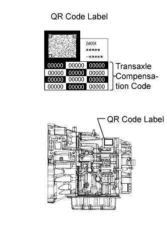
Record the transaxle compensation code specified on the QR label.
Tip:The transaxle compensation code is imprinted on the QR label.
-
Move the shift lever to N or P.
-
Connect the intelligent tester to the DLC3.
-
Turn the engine switch on (IG).
-
Turn the tester on.
Note:Do not start the engine.
-
Enter the following menus: Powertrain / ECT / Utility / A/T Code Registration.
-
Select "Set Compensation Code".
-
Register the compensation code.
-
Press "Input".
-
Manually input the transaxle compensation code. The code is a 60-digit alphanumeric value printed on the QR label. After inputting the code, press "OK".
-
-
Check that the compensation code displayed on the screen is correct by comparing it with the 60-digit alphanumeric value on the QR label.
Note:If an incorrect transaxle compensation code is input into the TCM, shift shock will occur.
-
Press "NEXT" to set the compensation code to the TCM.
Tip:
-
If the registration process fails, the compensation code may be incorrect. Check the compensation code again.
-
If the attempted compensation code is correct, a problem with the wire harness or a bad connection with the DLC3 may cause a registration failure. Check the wire harness and the DLC3 connection. If no problem is found, the TCM may be malfunctioning. Check the TCM and repeat this operation.
-
-
Press "EXIT".
-
-
Transfer Transaxle compensation code (Procedure 2)
Note:Transaxle compensation codes are 60-digit alphanumeric values imprinted on a QR label on the transaxle. If an incorrect transaxle compensation code is input into the TCM, shift shock may occur.
Tip:The following operation is available for use with TCMs that can transmit the registered transaxle compensation code to the intelligent tester.
-
Move the shift lever to N or P.
-
Connect the intelligent tester to the DLC3.
-
Turn the engine switch on (IG).
-
Turn the intelligent tester on.
Note:Do not start the engine.
Tip:The transaxle compensation code is imprinted on the QR label.
-
Read the transaxle compensation code.
-
Enter the following menus: Powertrain / ECT / Utility / A/T Code Registration.
-
Select "Read Compensation Code".
-
Press "Save".
-
Press "Save" or "Overwrite".
Tip:Press "Overwrite".
Note:Do not use the code specified on the transaxle QR label even if the transaxle compensation code cannot be read using the intelligent tester. The code printed on an in-service transaxle may not match its current characteristics. Replace the TCM with a new one and perform a road test to allow the TCM to learn.
-
Press "EXIT".
-
Turn the engine switch off.
-
-
Replace the TCM.
-
Set the transaxle compensation code.
-
Turn the engine switch on (IG).
-
Turn the intelligent tester on.
-
Enter the following menus: Powertrain / ECT / Utility / A/T Code Registration.
-
Select "Set Compensation Code".
-
Press "Open".
-
Press "Open" again to proceed.
-
Press "Exit".
-
-
-
-
RESET MEMORY (Continuously Variable Transaxle System)
-
Perform reset memory as follows:
-
Turn the engine switch off.
-
Move the shift lever to P and apply the parking brake.
-
Connect the intelligent tester to the DLC3.
-
Turn the engine switch on (IG).
Note:Do not start the engine.
-
Turn the intelligent tester on.
-
Enter the following menus: Powertrain / Engine and ECT / Utility / Reset Memory.
Note:
-
Keep the vehicle stopped, level and stable during the calibration.
-
Make sure that the shift lever is in P.
-
Make sure that the engine is stopped. To prevent idling vibrations, do not start the engine.
-
Make sure that the engine switch is on (IG).
-
-
-
-
DECELERATION SENSOR 0 POINT CALIBRATION (Continuously Variable Transaxle System)
-
Perform yaw rate sensor calibration (deceleration sensor 0 point calibration) as follows:
-
Turn the engine switch on (IG) and wait at least 2 seconds.
-
Enter the following menus: Powertrain / Engine and ECT / Utility / Deceleration Sensor 0 Point Calibration.
Tip:
-
When "Complete" is displayed on the intelligent tester, the deceleration sensor 0 point calibration is completed.
-
If "Error" is displayed on the intelligent tester, the deceleration sensor circuit may have a malfunction.
-
Shaking or vibrating the vehicle during 0 point calibration may cancel the calibration. If "Error" is displayed on the intelligent tester, perform calibration.
-
-
-
-
CVT OIL PRESSURE CALIBRATION (Continuously Variable Transaxle System)
-
Perform CVT oil pressure calibration as follows:
-
Turn the engine switch off and wait at least 30 seconds.
-
Turn the engine switch on (IG) and wait at least 2 seconds.
Note:Do not start the engine.
-
Start the engine and wait at least 5 seconds.
-
Enter the following menus: Powertrain / Engine and ECT / Utility / CVT Oil Pressure Calibration.
Tip:
-
During CVT oil pressure calibration, the engine idle speed will increase.
-
When "Complete" is displayed on the intelligent tester, the CVT oil pressure calibration is completed.
-
The learned values cannot be cleared by only disconnecting and reconnecting the cable to the negative (-) battery terminal.
-
-
-
-
ENGINE VARIANT LEARNING (Vehicle Stability Control System)
-
Perform engine variant learning.
Tip:
-
Engine variant learning is automatically performed immediately after the Test Mode is entered.
-
The ABS warning, brake warning and SLIP indicator lights come on for 3 seconds after learning.
-
-
-
ROTATION ANGLE SENSOR INITIALIZATION AND TORQUE SENSOR ZERO POINT CALIBRATION (Power Steering System)
Note:Clear the rotation angle sensor calibration value, initialize the rotation angle sensor, and calibrate the torque sensor zero point if any of the following has occurred:
-
The power steering ECU has been replaced.
-
The steering column assembly has been replaced.
-
Steering effort differs between turning left and right.
-
Inspection before calibration
-
Turn the engine switch off.
-
Connect the intelligent tester to the DLC3.
-
Turn the engine switch on (IG).
-
Turn the intelligent tester on.
-
Calibrate the power steering ECU. Enter the following menus: Chassis / EMPS / Data List.
-
Check the values by referring to the table below.
Table 1. EMPS Tester Display Measurement Item/Range Normal Condition Diagnostic Note IG Power Supply ECU power source voltage/
Min.: 0 V
Max.: 20.1531 V
10 to 14 V Engine switch on (IG) Standard voltage 10 to 14 V Note:If the IG power supply voltage is 9 V or less, calibration cannot be performed. In this case, charge or replace the battery, and then perform calibration.
-
-
Rotation angle sensor calibration value clear, rotation angle sensor initialization, and torque sensor zero point calibration
Note:
-
If DTC C1516 (Torque Sensor Zero Point Adjustment Incomplete) is stored, the torque sensor zero point cannot be calibrated. Clear the DTC before starting calibration.
-
If DTC C1526 (Rotation Angle Sensor Initialization Incomplete) is stored, the rotation angle sensor cannot be initialized. Clear the DTC before starting initialization.
-
Turn the engine switch off.
-
Connect the intelligent tester to the DLC3.
-
Turn the engine switch on (IG).
-
Turn the intelligent tester on.
-
Enter the following menus: Chassis / EMPS / Utility / Torque Sensor Adjustment.
Note:
-
Set the steering wheel to the center point and align the front tires straight ahead.
-
Do not turn the steering wheel sharply.
-
Do not touch the steering wheel during the torque sensor zero point calibration (for 3 seconds).
-
-
-
-
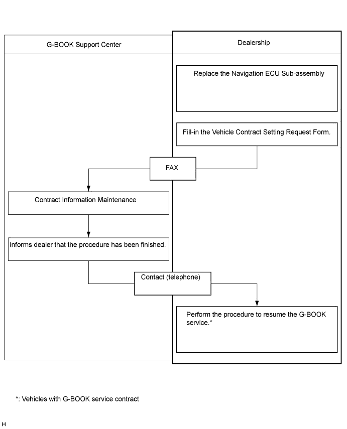
VEHICLE CONTRACT SETTING (G-BOOK System)
Tip:If the navigation ECU sub-assembly is replaced on vehicles that do not have a contract for the G-BOOK service, perform the vehicle contract setting.
-
Contact the G-BOOK center.
-
Contact the G-BOOK center to inform them that vehicle contract setting will be performed.
Tip:After contacting the G-BOOK center, the center will send a Vehicle Contract Setting Request Form by fax.
-
-
Check the ID before replacement (when diagnosis can be activated).
Tip:If the navigation ECU sub-assembly is replaced, check the G-BOOK ID.
-
Enter diagnostic mode (Click here).
-
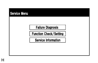
Select "Service Information" on the "Service Menu" screen.
-
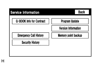
Select "G-BOOK Info for Contract" on the "Service Information" screen.
-
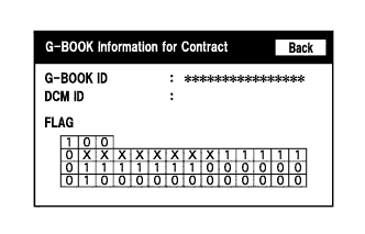
Check the G-BOOK ID.
-
-
Replace the navigation ECU sub-assembly.
-
Replace the navigation ECU sub-assembly at a dealership.
-
-
Check the ID after replacement.
Tip:If the navigation ECU sub-assembly is replaced, check the G-BOOK ID.
-
Enter diagnostic mode (Click here).
-
Select "Service Information" on the "Service Menu" screen.
-
Select "G-BOOK Info for Contract" on the "Service Information" screen.
-
Check the G-BOOK ID.
-
-
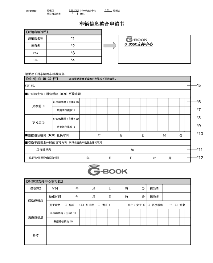
Fill-in the Vehicle Contract Setting Request Form.
-
After filling in the Vehicle Contract Setting Request Form, send it back to the G-BOOK center.
Item Information to Enter Note *1 Enter the dealership name of the applicant. Applicant information *2 Enter the name of the applicant. Applicant information *3 Enter the fax number of the dealership. Dealership information *4 Enter the phone number of the dealership. Dealership information *5 Enter the VIN of the vehicle. Vehicle information *6
-
Enter the G-BOOK ID of the old unit.
-
Left-align the number.
-
If the navigation ECU sub-assembly is not being replaced, it is not necessary to enter this item.
Used as change-request information from the dealership *7 - - *8
-
Enter the G-BOOK ID of the new unit installed to the vehicle.
-
Left-align the number.
-
If the navigation ECU sub-assembly is not being replaced, it is not necessary to enter this item.
Used as change-request information from the dealership *9 - - *10 - - *11 Enter the mileage on the odometer when the navigation ECU sub-assembly is replaced. Used as change-request information from the dealership *12 Enter the date that the mileage was recorded. Used as change-request information from the dealership -
-
-
Perform the procedure to resume the G-BOOK service.
Tip:The screen illustrations provided are samples only and may be different from actual screens.
-
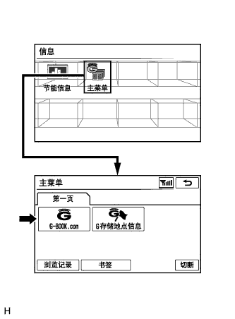
Perform the operations shown in the illustration and select G-BOOK.com.
-
Check that G-BOOK.com is displayed.
-
After the guidance screen is displayed, perform the procedure to resume the G-BOOK service by following the instructions on the screen.
-
-
-
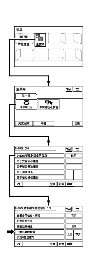
PERFORM "DOWNLOAD NECESSARY DATA" (G-BOOK System)
Tip:If the hard disk drive is replaced on vehicles that have a contract for the G-BOOK service, perform "Download necessary data" after installing the new hard disk drive.
-
Perform the operations shown in the illustration and select "Download necessary data".
Tip:The screen illustrations provided are samples only and may be different from actual screens.
-
-
ADJUST PARKING ASSIST MONITOR SYSTEM
-
This parking assist monitor system can be adjusted using the diagnostic screen of the display.
-
If the following operations are performed, it is necessary to perform adjustments and checks using the diagnostic screen.
Part Name Operation Adjustment Item Proceed to Spiral cable sub-assembly Removal and installation of the spiral cable sub-assembly Steering angle setting Procedure 3 Spiral cable sub-assembly Replacement Steering angle neutral point (Initialize parking assist monitor system) Steering angle setting Procedure 3 Navigation ECU sub-assembly Replacement Navigation ECU sub-assembly Procedure 1 Steering sensor Replacement Steering angle neutral point (Initialize parking assist monitor system) Steering angle setting Procedure 3 Steering sensor
-
Removal and installation of the steering sensor
-
Removal and installation of the connector of the steering sensor
Steering angle neutral point (Initialize parking assist monitor system) Steering angle setting Procedure 3 Suspension, tires, etc. The vehicle height changes because of suspension or tire replacement Rear television camera assembly optical axis (Back camera position setting) Procedure 2 Rear television camera assembly
-
Replacement
-
Installation angle of the rear television camera assembly changes because of the removal and installation of the rear television camera assembly, etc.
Rear television camera assembly optical axis (Back camera position setting) Procedure 2 Tip:The adjustment values stored while performing parking assist monitor system calibration are stored in the navigation ECU sub-assembly.
-
-
-
NAVIGATION ECU SUB-ASSEMBLY (PROCEDURE 1) (Parking Assist Monitor System)
Tip:Be sure to check for DTCs before performing this procedure (Click here).
-
Preparation for adjustment
-
Park the vehicle with the steering wheel centered.
-
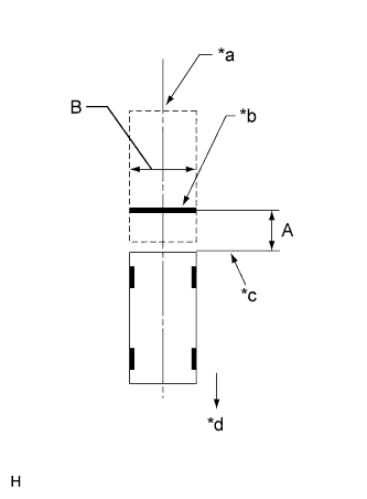
Set a target bar for optical axis adjustment of the rear television camera assembly.
Tip:Only when adjusting the optical axis of the camera, create a target bar for adjustment.
Dimension Area Specification A 963 to 973 mm (3.16 to 3.19 ft.) B 1995 to 2005 mm (6.545 to 6.578 ft.) Table 2. Text in Illustration *a Vehicle Center *b Target Bar for Back Camera Adjustment *c Vehicle End *d Front Tip:
-
Set a piece of tape on the ground as the target bar for adjustment. Its width and length should be 20 to 30 mm (0.787 to 1.181 in.) and 1995 to 2005 mm (6.545 to 6.578 ft.), respectively. Check the color on the navigation ECU sub-assembly and choose a tape color which can be easily seen.
-
Before parking the vehicle, be sure to move the vehicle forward and in reverse to check that the tires are facing straight ahead with the steering wheel centered.
-
Check that the back door is fully closed.
-
-
-
Start diagnostic mode (Click here).
Note:The following must be carried out with the engine started. Apply the parking brake, depress the brake pedal, check that the shift lever is in P, and ensure that the vehicle is not moving.
-
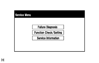
Select "Function Check/Setting" on the "Service Menu" screen.
-
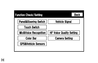
Select "Camera Setting" on the "Function Check/Setting" screen.
-
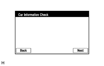
Select "Next" on the "Car Information Check" screen.
-
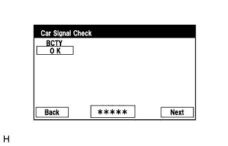
Select "Next" on the "Car Signal Check" screen.
Tip:
-
When "CHK" (red) is displayed for any items on the "Car Signal Check" screen, selecting "Next" will not change the screen to the "Steering Angle Setting" screen.
-
When "CHK" (red) is displayed for any items on the "Car Signal Check" screen, perform inspections using the "Car Signal Check" screen (Click here).
-
-
-
Steering Angle Setting
-
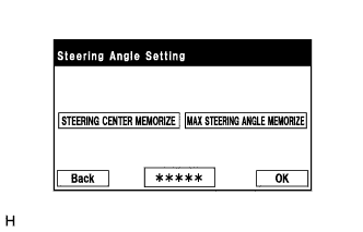
Perform the "STEERING CENTER MEMORIZE" operation.
-
Check that the steering wheel is centered, and then select "STEERING CENTER MEMORIZE".
Tip:When performing removal and installation, or replacement of the rear television camera assembly, steering angle setting is not required.
-
-
Perform the "MAX STEERING ANGLE MEMORIZE" operation.
-
After performing the steering center memorize operation, turn the steering wheel to the left and right lock positions and select "MAX STEERING ANGLE MEMORIZE". The maximum steering angle is then stored and the screen changes to the "Back Camera Position Setting" screen.
Tip:The "Next" button does not respond until the system memorizes the steering center and maximum steering wheel angle.
Tip:
-
It is also possible to start by initially turning the steering to the right side.
-
When "MAX STEERING ANGLE MEMORIZE" is selected, a beep will sound to confirm that the adjustment values have been stored.
-
The adjustment values will not be stored unless "MAX STEERING ANGLE MEMORIZE" is selected after turning the steering wheel from lock to lock.
-
When "BACK" is selected, the screen changes to the "Car Signal Check" screen without storing any values.
-
Even if no DTCs are detected, selecting "MAX STEERING ANGLE MEMORIZE" may not cause the adjustment values to be stored if the steering sensor is malfunctioning.
-
If selecting "MAX STEERING ANGLE MEMORIZE" does not cause the adjustment value to be stored after performing the steering angle setting procedure, replace the steering sensor (Click here).
-
-
-
-
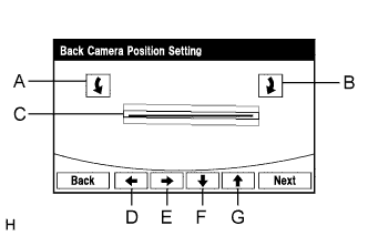
Back Camera Position Setting
Tip:
-
When adjusting the camera optical axis, "Back door is open. Do not use the rear view monitor when the back door is not completely closed." is displayed even after the back door has been closed.
-
When the back door is open, the "Back door is open. Do not use the rear view monitor when the back door is not completely closed." message will be displayed and camera position setting will not be possible.
-
If the "Back door is open. Do not use the rear view monitor when the back door is not completely closed." message is displayed even when the back door is closed, perform inspections according to Problem Symptoms Table (When adjusting the camera optical axis, "Back door is open. Do not use the rear view monitor when the back door is not completely closed." is displayed even after the back door has been closed.) (Click here).
-
Perform roll angle adjustment.
-
Use switches A and B to rotate C so that it is parallel to the target adjustment bar.
-
-
Perform vertical and horizontal position adjustment.
-
Use the directional switches D, E, F and G to move C so that the target adjustment bar is centered in C.
-
-
Select the "Next" button on the "Back Camera Position Setting" screen.
-
-
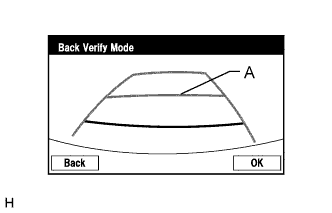
Back Verify Mode
-
Check that A and the target adjustment bar are overlapping.
-
If the lines are not aligned, perform the "STEERING CENTER MEMORIZE" and "MAX STEERING ANGLE MEMORIZE" operations.
-
If A and the target adjustment bar are not aligned even if the tires are aligned straight ahead, perform the back camera position setting operation.
-
-
Selecting "OK" will return to the "Service Menu" screen, and complete the adjustment.
Tip:
-
The update is not completed until "OK" is selected.
-
When "OK" is selected, a beep will sound to confirm that the adjustment values have been stored.
-
The adjustment values are not stored until the beep has sounded.
-
-
-
Finish diagnostic mode (Click here).
-
Confirm steering angle adjustment.
Tip:If the steering angle has been adjusted, confirm the steering angle adjustment on the parking assist monitor screen after finishing diagnosis mode.
-
Check on the parking assist screen that the predicted path line moves until the steering wheel is fully turned to either the left or right.
Tip:If the predicted path line stops moving before the steering wheel is fully turned to either the left or right, the steering angle adjustment values have not been stored correctly. In this case, perform "STEERING CENTER MEMORIZE" and "MAX STEERING ANGLE MEMORIZE" again.
-
-
-
BACK CAMERA POSITION SETTING (PROCEDURE 2) (Parking Assist Monitor System)
Tip:Be sure to check for DTCs before performing this procedure (Click here).
-
Preparation for adjustment
-
Park the vehicle with the steering wheel centered.
-
Set a target bar behind the vehicle for optical axis adjustment of the rear television camera assembly (back camera position setting).
Tip:Create a target bar for adjustment only when adjusting the optical axis of the camera.
Dimension Area Specification A 963 to 973 mm (3.16 to 3.19 ft.) B 1995 to 2005 mm (6.545 to 6.578 ft.) Table 3. Text in Illustration *a Vehicle Center *b Target Bar for Back Camera Position Setting *c Vehicle End *d Front Tip:
-
Set a piece of tape on the ground as the target bar for adjustment. Its width and length should be 20 to 30 mm (0.787 to 1.181 in.) and 1995 to 2005 mm (6.545 to 6.578 ft.), respectively. Check the color on the navigation ECU sub-assembly and choose a tape color which can be easily seen.
-
Before parking the vehicle, be sure to move the vehicle forward and in reverse to check that the tires are facing straight ahead with the steering wheel centered.
-
Check that the back door is fully closed.
-
-
-
Start diagnostic mode (Click here).
Note:The following must be carried out with the engine started. Apply the parking brake, depress the brake pedal, check that the shift lever is in P, and ensure that the vehicle is not moving.
-
Select "Function Check/Setting" on the "Service Menu" screen.
-
Select "Camera Setting" on the "Function Check/Setting" screen.
-
Select "Next" on the "Car Information Check" screen.
-
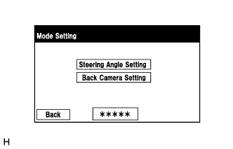
Select "Back Camera Setting" on the "Mode Setting" screen.
Tip:To select a grayed out item, select and hold the item for 2 seconds or more.
-
Select "Next" on the "Car Signal Check" screen.
Tip:
-
When "CHK" (red) is displayed for any items on the "Car Signal Check" screen, selecting "Next" will not change the screen to the "Back Camera Position Setting" screen.
-
When "CHK" (red) is displayed for any items on the "Car Signal Check" screen, perform inspections using the "Car Signal Check" screen (Click here).
-
-
-
Back Camera Position Setting
Tip:
-
When the back door is open, the "Back door is open. Do not use the rear view monitor when the back door is not completely closed." message will be displayed and camera position setting will not be possible.
-
If the "Back door is open. Do not use the rear view monitor when the back door is not completely closed." message is displayed even when the back door is closed, perform inspections according to Problem Symptoms Table (When adjusting the camera optical axis, "Back door is open. Do not use the rear view monitor when the back door is not completely closed." is displayed even after the back door has been closed.) (Click here).
-
Perform roll angle adjustment.
-
Use switches A and B to rotate C so that it is parallel to the target adjustment bar.
-
-
Perform vertical and horizontal position adjustment.
-
Use the directional switches D, E, F and G to move C so that the target adjustment bar is centered in C.
-
-
Select the "Next" button on the "Back Camera Position Setting" screen.
-
-
Back Verify Mode
-
Check that A and the target adjustment bar are overlapping.
-
If the lines are not aligned, perform the "STEERING CENTER MEMORIZE" and "MAX STEERING ANGLE MEMORIZE" operations.
-
If A and the target adjustment bar are not aligned even if the tires are aligned straight ahead, perform the back camera position setting operation.
-
-
Selecting "OK" will return to the "Service Menu", and complete the adjustment.
Tip:
-
The update is not completed until "OK" is selected.
-
When "OK" is selected, a beep will sound to confirm that the adjustment values have been stored.
-
The adjustment values are not stored until the beep has sounded.
-
-
-
Finish diagnostic mode (Click here).
-
-
STEERING ANGLE SETTING (PROCEDURE 3) (Parking Assist Monitor System)
Tip:If the vehicle width extension lines and predicted path lines are not aligned when the steering wheel is centered, or if the predicted path line does not move before the steering wheel is fully turned to either the left or right, perform Steering Angle Setting.
-
Center the steering wheel and stop the vehicle.
-
Start diagnostic mode (Click here).
Note:The following must be carried out with the engine started. Apply the parking brake, depress the brake pedal, check that the shift lever is in P, and ensure that the vehicle is not moving.
-
Select "Function Check/Setting" on the "Service Menu" screen.
-
Select "Camera Setting" on the "Function Check/Setting" screen.
-
Select "Next" on the "Car Information Check" screen.
-
Select "Steering Angle Setting" on the "Mode Setting" screen.
Tip:To select a grayed out item, select and hold the item for 2 seconds or more.
-
Select "Next" on the "Car Signal Check" screen to display the "Steering Angle Setting" screen.
Tip:
-
When "CHK" (red) is displayed for any items on the "Car Signal Check" screen, selecting "Next" will not change the screen to the "Steering Angle Setting" screen.
-
When "CHK" is displayed for any items on the "Car Signal Check" screen, perform inspections using the "Car Signal Check" screen (Click here).
-
-
-
Steering Angle Setting
-
Check that the steering wheel is centered (approximately +/- 5 degrees or less) and select "STEERING CENTER MEMORIZE".
-
After the centered steering position is memorized, turn the steering wheel to the left and then to the right full lock positions and select "MAX STEERING ANGLE MEMORIZE".
Tip:It is also possible to start by initially turning the steering wheel to the right side.
-
Select "MAX STEERING ANGLE MEMORIZE" to store the steering angle adjustment value and change the screen to the "Mode Setting" screen.
Tip:
-
When "MAX STEERING ANGLE MEMORIZE" is selected, a beep will sound to confirm that the steering angle adjustment values have been stored.
-
The adjustment values will not be stored unless "MAX STEERING ANGLE MEMORIZE" is selected.
-
When "BACK" is selected, the screen changes to Car Signal Check without storing the set values.
-
If the "Steering Angle Setting"s have not been adjusted, selecting "MAX STEERING ANGLE MEMORIZE" will not cause the adjustment values to be stored.
-
Even if no DTCs are detected, selecting "MAX STEERING ANGLE MEMORIZE" may not cause the adjustment value to be stored if the steering sensor is malfunctioning.
-
If selecting "MAX STEERING ANGLE MEMORIZE" does not cause the adjustment value to be stored after adjusting the steering angle, replace the steering sensor (Click here).
-
-
-
Finish diagnostic mode (Click here).
-
Confirm steering angle adjustment.
Tip:If the steering angle has been adjusted, confirm the steering angle adjustment on the parking assist monitor screen after finishing diagnosis mode.
-
Check on the parking assist screen that the predicted path line moves until the steering wheel is fully turned to either the left or right.
Tip:If the predicted path line stops moving before the steering wheel is fully turned to either the left or right, the steering angle adjustment values have not been stored correctly. In this case, perform "STEERING CENTER MEMORIZE" and "MAX STEERING ANGLE MEMORIZE" again.
-
-
-
SEAT POSITION INITIALIZATION (Rear Power Seat Control System (w/ Memory))
Note:When either of the following operations is performed, clear the seat position memory and register the seat position.
-
Replacement of the rear position control ECU assembly
-
Disassembly/reassembly of the rear No. 1 seat assembly
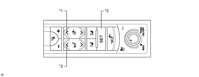
Table 4. Text in Illustration *1 Reclining Switch (Forward) *2 Ottoman Switch (Up) *3 SET Switch - -
-
Clear the seat position memory
Tip:
-
Move the seatback to the foremost position and the ottoman to the uppermost position before starting the seat position memory clear operation.
-
If the SET switch is pressed but not held on the 5th time, perform the procedure from the step marked *1 again.
-
If the ottoman switch (up) has not been pressed 5 times when 10 seconds have elapsed after the reclining switch (forward) was pressed and held, perform the procedure from the step marked *1 again.
-
If any operations other than the following are performed, perform the procedure from the step marked *1 again.
-
Press and hold the reclining switch (forward).*1
-
Press and hold the ottoman switch (up) while the reclining switch (forward) is being pressed.
-
Press the SET switch 5 times (press and hold the switch on the 5th time) while the reclining switch (forward) and ottoman switch (up) are being pressed.
-
When 10 seconds have elapsed after the reclining switch (forward) was pressed and held, check that the buzzer sounds for 0.5 seconds and the seat position memory is cleared.
-
-
Register the seat position
-
Press and hold the reclining switch to move the seatback to the foremost or fully reclined position and keep the seatback at the same position until the buzzer sounds for 0.1 seconds.
-
Press and hold the ottoman switch to move the ottoman to the uppermost or fully stored position, and keep the ottoman at the same position until the buzzer sounds for 0.5 seconds.
-
-
-
AFS ECU OR HEADLIGHT LEVELING ECU INITIALIZATION (Lighting System)
Note:
-
Initialize the AFS ECU or headlight leveling ECU assembly (set the zero point of the height control sensor in the AFS ECU or headlight leveling ECU assembly) after the vehicle height changes due to replacement of the suspension or after performing such operations as removal and reinstallation or replacement of the rear height control sensor sub-assembly LH.
-
When the AFS ECU or headlight leveling ECU assembly is replaced, the initialization is also necessary.
-
Adjust the headlight aim after initializing the AFS ECU or headlight leveling ECU assembly (Click herefor ALPHARD,Click herefor VELLFIRE).
-
When a malfunction is detected in the automatic headlight beam level control system, the height control sensor signal initialization is impossible. Perform troubleshooting before initialization.
- Click here
PREPARE VEHICLE FOR INITIALIZATION
-
Unload the trunk and vehicle, ensuring that the spare tire, tools and jack are in their original positions.
-
Check that there are no occupants in the vehicle.
-
Turn off the headlights.
-
Stop the vehicle on a level surface and keep the vehicle height unchanged.
- NEXT
-
- Click here
CHECK INDICATOR LIGHT
-
Turn the engine switch on (IG), and check the AFS OFF indicator light.
OK Condition Specified Condition The AFS ECU or headlight leveling ECU assembly is replaced with a new one. Indicator light continuously blinks 6 times at 2 Hz. Replacement of the rear height control sensor sub-assembly LH, removal and reinstallation of the rear height control sensor sub-assembly LH, replacement of the suspension, etc. is performed. Indicator light comes on for approximately 3 seconds, and then goes off (bulb check function). Tip:If the indicator light does not come on when turning the engine switch on (IG), inspect and repair it according to Problem Symptoms Table (Click here).
- NG
- GO TO PROBLEM SYMPTOMS TABLE
- OK
-
- Click here
INITIALIZATION
-
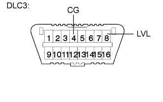
Connect terminals 4 (CG) and 8 (LVL) of the DLC3 using SST.
09843-18040 -
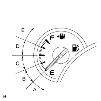
Turn the low beam headlights on and off using the light control switch within 20 seconds after connecting the terminals.
Tip:The number of times the low beam headlights need to be turned on and off is determined by the present fuel level as shown below.
Fuel Level Number of Times to Turn Low Beam Headlights on and off Fuel level is within A range. 1 Fuel level is within B range. 2 Fuel level is within C range. 3 Fuel level is within D range. 4 Fuel level is within E range. 5 Note:
-
Turn the low beam headlights on and off at approximately 1-second intervals.
-
Be sure to operate the light control switch from outside the vehicle.
-
-
Check the indicator light.
OK Condition Specified Condition The AFS ECU or headlight leveling ECU assembly is replaced with a new one. Blinks 6 times at 2 Hz → Continuously Blinks N*1 times at 2 Hz. Replacement of the rear height control sensor sub-assembly LH, removal and reinstallation of the rear height control sensor sub-assembly LH, replacement of the suspension, etc. is performed. Off → Continuously Blinks N*1 times at 2 Hz. Tip:
-
*1: The number of times that AFS OFF indicator blinks is determined by the number of times the low beam headlights are turned on and off.
-
If initialization cannot be finished normally, Disconnect SST from the DLC3 and turn the engine switch off. Then, restart from procedure 1.
- NG
- GO TO PROBLEM SYMPTOMS TABLE
- OK
- TURN ENGINE SWITCH OFF (END)
-
-
-
-
INITIALIZE POWER WINDOW CONTROL SYSTEM (Power Window Control System)
CAUTION:When the power window regulator motor assembly is reinstalled or replaced, the power window control system must be initialized. Functions such as the auto up/down, jam protection, remote control and key-off operation do not operate if the initialization is not performed.
Tip:When the battery is replaced, it is not necessary to initialize the power window regulator motor assembly.
Note:
-
When the power window regulator motor assembly is replaced, DTC B2313 is output. Clear the DTC after the initialization.
-
When performing initialization, do not perform any other procedures.
-
After a door glass or a door glass run has been replaced, the jam protection function may operate unexpectedly when the auto up function is used, due to detection of a value different from the operation learned value of the door glass movement speed. In such cases, the auto up function can be reinitialized by repeating the following operation at least 5 times:
-
-
Open the power window by fully pushing down the multiplex network master switch assembly or power window regulator switch assembly.
-
Close the power window by fully pulling up the multiplex network master switch assembly or power window regulator switch assembly and holding it at the auto up position.
-
-
If the initialization is not completed properly, the LIN communication system may have a malfunction (Click here).
-
Initialization procedure when replacing the power window regulator motor assembly with a new one:
-
Connect the battery and turn the engine switch on (IG) (at this time, the LED on the multiplex network master switch assembly or power window regulator switch assembly blinks to indicate that it is ready for initialization).
-
Fully open the window by fully pushing down the multiplex network master switch assembly or power window regulator switch assembly, and hold the switch for 1 second or more after the window is fully opened.
-
Fully close the power window by fully pulling up the multiplex network master switch assembly or power window regulator switch assembly, and hold the switch for 1 second or more after the window is fully closed to reset the glass position. The LED on the multiplex network master switch assembly or power window regulator switch assembly stops blinking and illuminates to indicate that the initialization is complete.
-
-
Initialization procedure when removing/installing the power window regulator motor assembly:
-
Connect the battery and turn the engine switch on (IG).
-
Fully close the power window by fully pulling up the multiplex network master switch assembly or power window regulator switch assembly, and hold the switch for 6 seconds or more after the window is fully closed (if the power window does not move or stops halfway even when the switch is fully pulled, release the switch and fully pull it again).
-
Fully open the window by pushing down the multiplex network master switch assembly or power window regulator switch assembly, and hold the switch for 1 second or more after the window is fully opened.
-
Release the multiplex network master switch assembly or power window regulator switch assembly. Then fully push down and hold the switch for 4 seconds or more.
-
Fully close the power window by fully pulling up the multiplex network master switch assembly or power window regulator switch assembly, and hold the switch for 1 second or more after the window is fully closed to reset the glass position and complete the initialization.
-
-
Initialization procedure when the power window does not fully open:
-
Connect the battery and turn the engine switch on (IG).
-
Fully close the power window by fully pulling up the multiplex network master switch assembly or power window regulator switch assembly, and hold the switch for 6 seconds or more after the window is fully closed (if the power window does not move or stops halfway even when the switch is fully pulled, release the switch and fully pull it again).
-
Fully open the window by pushing down the multiplex network master switch assembly or power window regulator switch assembly, and hold the switch for 1 second or more after the window is fully opened.
-
Release the multiplex network master switch assembly or power window regulator switch assembly. Then fully push down and hold the switch for 4 seconds or more.
-
Fully close the power window by fully pulling up the multiplex network master switch assembly or power window regulator switch assembly, and hold the switch for 1 second or more after the window is fully closed to reset the glass position and complete the initialization.
-
-
-
INITIALIZING SLIDING ROOF ECU (Sliding Roof System)
Note:
-
When the sliding roof ECU (sliding roof drive gear assembly) is replaced or removed and reinstalled, it requires initialization. If initialization is not performed, the following functions may not operate, or may not operate correctly: auto operation and jam protection function.
-
If the following conditions occur during the initialization procedure, initialization will fail:
-
-
One of the following electric loads is applied to the vehicle during initialization: cranking the engine, power window operation, rear defogger operation, blower operation, power seat operation, power door lock operation or headlight illumination.
-
The engine switch is turned off.
-
Another switch is turned on during initialization.
-
The vehicle experiences a strong vibration during initialization, such as slamming of a door.
-
-
Check the operation of the sliding roof.
Sliding Roof Operation Proceed to Auto operation does not operate. Procedure A Auto operation operates normally, but the sliding roof glass does not stop at the correct fully closed position. Procedure B Auto operation operates normally, but the sliding roof erroneously reverses operation while sliding closed. Procedure C Tip:Before performing initialization, make sure that there is no foreign matter on the guide rails and the guide rails are not deformed.
-
Procedure A (Normal initialization)
-
Turn the engine switch on (IG).
-
Press and hold the CLOSE switch.
-
The sliding roof glass starts sliding close operation and stops at the fully closed position.
-
After the sliding roof glass stops, continue pressing the CLOSE switch for 1 second or more.
-
Check that the sliding roof glass moves slightly rearward and stops at the correct fully closed position.
Tip:The initialization process ends when this operation completes.
-
-
Procedure B (Resetting the memorized position)
-
Turn the engine switch on (IG).
-
Press and hold the CLOSE switch until the sliding roof glass stops and then release the switch.
-
Press and hold the CLOSE switch again for 10 seconds or more.
-
The sliding roof glass starts sliding closed operation and stops at the fully closed position.
-
After the sliding roof glass stops, continue pressing the CLOSE switch for 1second or more.
-
Check that the sliding roof glass moves slightly rearward and stops at the correct fully closed position.
Tip:The initialization process ends when this operation completes.
-
-
Procedure C (Clear initialization)
-
Turn the engine switch on (IG).
-
Press and hold the CLOSE switch until the following movements finish and then release the switch: starts sliding closed → erroneously reverses → stops operation for 10 seconds → starts sliding closed → stops at the fully closed position.
-
Perform Procedure A.
-
-