SEAT HEATER SYSTEM ON-VEHICLE INSPECTION

-
INSPECT SEAT HEATER CONTROL SUB-ASSEMBLY LH
-
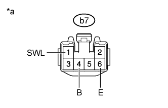
Text in Illustration *a Front view of wire harness connector
(to Seat Heater Control Sub-assembly LH)
Disconnect the b7 heater control connector.
-
Measure the resistance according to the value(s) in the table below.
Standard Resistance Tester Connection Condition Specified Condition b7-6 (E) - Body ground Always Below 1 Ω -
Measure the voltage according to the value(s) in the table below.
Standard Voltage Tester Connection Switch Condition Specified Condition b7-1 (SWL) - b7-6 (E) Ignition switch ON
Seat heater switch LH off
Below 1 V Ignition switch ON
Seat heater switch LH on
11 to 14 V b7-4 (B) - b7-6 (E) Ignition switch off Below 1 V Ignition switch ON 11 to 14 V If the result is not as specified, there may be a malfunction on the wire harness side.
-
Connect the b7 heater control connector.
-
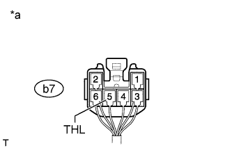
Text in Illustration *a Component with harness connected
(Seat Heater Control Sub-assembly LH)
Measure the voltage according to the value(s) in the table below.
Standard Voltage Tester Connection Switch Condition Specified Condition b7-5 (THL) - Body ground Ignition switch ON
Seat heater switch LH on, MIN → MAX
Gradual increase between value below 1 V and value from 11 to 14 V If the result is not as specified, the seat heater control may have a malfunction.
-
-
INSPECT SEAT HEATER CONTROL SUB-ASSEMBLY RH
-
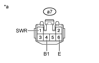
Text in Illustration *a Front view of wire harness connector
(to Seat Heater Control Sub-assembly RH)
Disconnect the a7 heater control connector.
-
Measure the resistance according to the value(s) in the table below.
Standard Resistance Tester Connection Condition Specified Condition a7-6 (E) - Body ground Always Below 1 Ω -
Measure the voltage according to the value(s) in the table below.
Standard Voltage Tester Connection Switch Condition Specified Condition a7-1 (SWR) - a7-6 (E) Ignition switch ON
Seat heater switch RH off
Below 1 V Ignition switch ON
Seat heater switch RH on
11 to 14 V a7-4 (B1) - a7-6 (E) Ignition switch off Below 1 V Ignition switch ON 11 to 14 V If the result is not as specified, there may be a malfunction on the wire harness side.
-
Connect the a7 heater control connector.
-
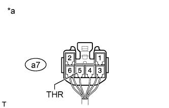
Text in Illustration *a Component with harness connected
(Seat Heater Control Sub-assembly RH)
Measure the voltage according to the value(s) in the table below.
Standard Voltage Tester Connection Switch Condition Specified Condition a7-5 (THR) - Body ground Ignition switch ON
Seat heater switch RH on, MIN → MAX
Gradual increase between value below 1 V and value from 11 to 14 V If the result is not as specified, the seat heater control may have a malfunction.
-