PRE-CRASH SAFETY SYSTEM, Diagnostic DTC:U1104, U1104

| DTC Code | DTC Name |
|---|---|
| U1104 | Lost Communication with Driving Support ECU |
| U1104 | Lost Communication with Driving Support ECU |
DESCRIPTION
| DTC Code | DTC Detection Condition | Trouble Are |
|---|---|---|
| U1104 | When the ignition switch is ON, a communication error between the millimeter wave radar sensor assembly and driving support ECU is detected for 1 second. |
|
| U1104 | When the ignition switch is ON, communication stops between the seat belt control ECU and driving support ECU for 1 second or more. |
|
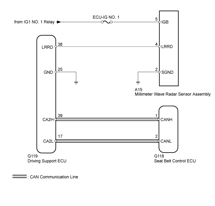
WIRING DIAGRAM
INSPECTION PROCEDURE
Note
-
When the millimeter wave radar sensor assembly is replaced with a new one, adjustment of the radar sensor beam axis must be performed Click here.
-
Inspect the fuses for circuits related to this system before performing the following inspection procedure.
-
Confirm that the connector is securely connected, as a partially connected connector may be the cause of this DTC being output.
PROCEDURE
-
CHECK FOR DTC
-
Clear the DTCs Click here.
-
Check for DTCs Click here.
Result Result Proceed to DTC U1104 is not output A DTC U1104 is output from driving support ECU (Pre-Crash 2) B DTC U1104 is output from seat belt control ECU (Pre-Crash) C
B 
CHECK HARNESS AND CONNECTOR (MILLIMETER WAVE RADAR SENSOR - BATTERY AND BODY GROUND) Click here
C
CHECK CAN COMMUNICATION SYSTEM Click here
A 
USE SIMULATION METHOD TO CHECK Click here
-
-
CHECK HARNESS AND CONNECTOR (MILLIMETER WAVE RADAR SENSOR - BATTERY AND BODY GROUND)
-
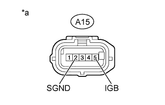
Text in Illustration *a Front view of wire harness connector
(to Millimeter Wave Radar Sensor Assembly)
Disconnect the A15 sensor connector.
-
Measure the voltage according to the value(s) in the table below.
Standard Voltage Tester Connection Switch Condition Specified Condition A15-5 (IGB) - Body ground Ignition switch ON 11 to 14 V Ignition switch off Below 1 V -
Measure the resistance according to the value(s) in the table below.
Standard Resistance Tester Connection Condition Specified Condition A15-2 (SGND) - Body ground Always Below 1 Ω
NG 
REPAIR OR REPLACE HARNESS OR CONNECTOR
OK 
-
-
CHECK HARNESS AND CONNECTOR (DRIVING SUPPORT ECU - BODY GROUND)
-
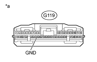
Text in Illustration *a Front view of wire harness connector
(to Driving Support ECU)
Disconnect the G119 ECU connector.
-
Measure the resistance according to the value(s) in the table below.
Standard Resistance Tester Connection Condition Specified Condition G119-25 (GND) - Body ground Always Below 1 Ω
NG
REPAIR OR REPLACE HARNESS OR CONNECTOR
OK
-
-
CHECK HARNESS AND CONNECTOR (MILLIMETER WAVE RADAR SENSOR - DRIVING SUPPORT ECU)
-
Disconnect the A15 sensor connector.
-
Disconnect the G119 ECU connector.
-
Measure the resistance according to the value(s) in the table below.
Standard Resistance Tester Connection Condition Specified Condition A15-4 (LRRD) - G119-38 (LRRD) Always Below 1 Ω A15-4 (LRRD) - Body ground Always 10 kΩ or higher
NG
REPAIR OR REPLACE HARNESS OR CONNECTOR
OK
-
-
REPLACE DRIVING SUPPORT ECU
-
Replace the driving support ECU Click here.
NEXT
-
-
CHECK FOR DTC
-
Clear the DTCs Click here.
-
Check for DTCs Click here.
OK DTC U1104 is not output.
NG
REPLACE MILLIMETER WAVE RADAR SENSOR ASSEMBLY Click here
OK
END (DRIVING SUPPORT ECU IS DEFECTIVE)
-
-
CHECK CAN COMMUNICATION SYSTEM
-
Select "Bus Check" from the "System Select" screen on the intelligent tester.
-
Select "Communication Malfunction DTC" from the "Bus Check" screen, and then select "Enter".
Result Result Proceed to CAN DTC is not output A CAN DTC is output (for LHD with Entry and Start System) B CAN DTC is output (for LHD without Entry and Start System) C CAN DTC is output (for RHD with Entry and Start System) D CAN DTC is output (for RHD without Entry and Start System) E
B
GO TO CAN COMMUNICATION SYSTEM Click here
C
GO TO CAN COMMUNICATION SYSTEM Click here
D
GO TO CAN COMMUNICATION SYSTEM Click here
E
GO TO CAN COMMUNICATION SYSTEM Click here
A
USE SIMULATION METHOD TO CHECK Click here
-