FRONT POWER SEAT CONTROL SYSTEM (w/ Memory) Front Power Seat does not Operate with Front Power Seat Switch
DESCRIPTION
When a signal is input into the front power seat switch (seat ECU), the ECU manages the signals received from the front power seat switch and operates each motor. When 2 or more signals are input, the motors only operate when the signals are from the slide switch and reclining switch.
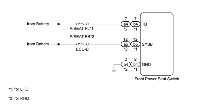
WIRING DIAGRAM
INSPECTION PROCEDURE
Tech Tips
Inspect the fuses for circuits related to this system before performing the following inspection procedure.
PROCEDURE
-
READ VALUE USING INTELLIGENT TESTER (FRONT POWER SEAT SWITCH)
-
Using the intelligent tester, read the Data List Click here.
Driver Seat Tester Display Measurement Item/Range Normal Condition Diagnostic Note Reclining Rear Reclining switch signal (Rearward) / ON or OFF ON: Reclining switch (Rearward) on
OFF: Reclining switch (Rearward) off
- Reclining Front Reclining switch signal (Forward) / ON or OFF ON: Reclining switch (Forward) on
OFF: Reclining switch (Forward) off
- Front Vertical Down Front vertical switch signal (Downward) / ON or OFF ON: Front vertical switch (Downward) on
OFF: Front vertical switch (Downward) off
- Front Vertical Up Front vertical switch signal (Upward) / ON or OFF ON: Front vertical switch (Upward) on
OFF: Front vertical switch (Upward) off
- Lifter Switch Down Lifter switch signal (Downward) / ON or OFF ON: Lifter switch (Downward) on
OFF: Lifter switch (Downward) off
- Lifter Switch Up Lifter switch signal (Upward) / ON or OFF ON: Lifter switch (Upward) on
OFF: Lifter switch (Upward) off
- Slide Rear Sliding switch signal (Rearward) / ON or OFF ON: Sliding switch (Rearward) on
OFF: Sliding switch (Rearward) off
- Slide Front Sliding switch signal (Forward) / ON or OFF ON: Sliding switch (Forward) on
OFF: Sliding switch (Forward) off
- OK On intelligent tester screen, each item changes between ON and OFF according to above chart.
NG 
CHECK HARNESS AND CONNECTOR (FRONT POWER SEAT SWITCH - BATTERY AND BODY GROUND) Click here
OK 
USE SIMULATION METHOD TO CHECK Click here
-
-
CHECK HARNESS AND CONNECTOR (FRONT POWER SEAT SWITCH - BATTERY AND BODY GROUND)
-
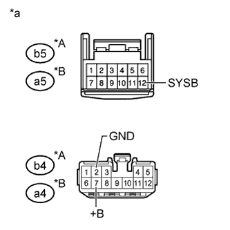
Text in Illustration *A for LHD *B for RHD *a Front view of wire harness connector
(to Front Power Seat Switch)
for LHD:
Disconnect the b4 and b5 switch connectors.
-
for RHD:
Disconnect the a4 and a5 switch connectors.
-
Measure the voltage according to the value(s) in the table below.
Standard Voltage for LHD Tester Connection Condition Specified Condition b4-7 (+B) - Body ground Always 11 to 14 V b5-12 (SYSB) - Body ground Always 11 to 14 V for RHD Tester Connection Condition Specified Condition a4-7 (+B) - Body ground Always 11 to 14 V a5-12 (SYSB) - Body ground Always 11 to 14 V -
Measure the resistance according to the value(s) in the table below.
Standard Resistance for LHD Tester Connection Condition Specified Condition b4-2 (GND) - Body ground Always Below 1 Ω for RHD Tester Connection Condition Specified Condition a4-2 (GND) - Body ground Always Below 1 Ω
NG 
REPAIR OR REPLACE HARNESS OR CONNECTOR
OK
REPLACE FRONT POWER SEAT SWITCH Click here
-