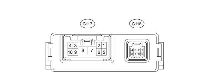
PRE-CRASH SAFETY SYSTEM TERMINALS OF ECU

-
CHECK SEAT BELT CONTROL ECU
-
Disconnect the G117 and G118 ECU connectors.
-
Measure the voltage and resistance according to the value(s) in the table below.
Terminal No. (Symbol) Wiring Color Terminal Description Condition Specified Condition G117-7 (+B) - Body ground W - Body ground Battery Always 11 to 14 V G117-8 (PGND) - Body ground W-B - Body ground Body ground Always Below 1 Ω G118-8 (IG1) - Body ground G - Body ground Seat belt control ECU power supply Ignition switch ON 11 to 14 V Ignition switch off Below 1 V If the result is not as specified, there may be a malfunction on the wire harness side.
-
Reconnect the G117 and G118 ECU connectors.
-
Measure the voltage according to the value(s) in the table below.
Terminal No. (Symbol) Wiring Color Terminal Description Condition Specified Condition G117-2 (MOR+) - Body ground B - Body ground Seat belt motor RH power supply Ignition switch ON 4.0 to 8.5 V Ignition switch off Below 1 V G117-1 (MOR-) - Body ground LG - Body ground Seat belt motor RH power supply Ignition switch ON 4.0 to 8.5 V Ignition switch off Below 1 V G117-3 (MOL+) - Body ground R - Body ground Seat belt motor LH power supply Ignition switch ON 4.0 to 8.5 V Ignition switch off Below 1 V G117-4 (MOL-) - Body ground G - Body ground Seat belt motor LH power supply Ignition switch ON 4.0 to 8.5 V Ignition switch off Below 1 V G118-5 (PBK+) - G118-6 (PBK-) G - R*1
V - P*2
Front seat inner belt (for passenger side) signal Ignition switch ON, front seat belt (for passenger side) fastened Pulse generation
(See waveform 1)
Ignition switch ON, front seat belt (for passenger side) unfastened Pulse generation
(See waveform 2)
G118-6 (PBK-) - Body ground R - Body ground*1
P - Body ground*2
Front seat inner belt (for passenger side) signal Always Below 1 Ω
-
*1: for LHD
-
*2: for RHD
If the result is not as specified, the ECU may be malfunctioning.
-
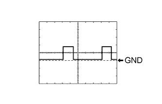
Using an oscilloscope, check waveform 1.
Measurement Condition Item Content Tester Connection G118-5 (PBK+) - G118-6 (PBK-) Tool Setting 2 V/DIV., 20 ms/DIV. Vehicle Condition Ignition switch ON, front seat belt (for passenger side) fastened -
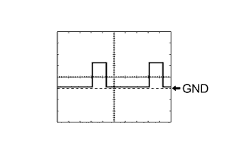
Using an oscilloscope, check waveform 2.
Measurement Condition Item Content Tester Connection G118-5 (PBK+) - G118-6 (PBK-) Tool Setting 2 V/DIV., 20 ms/DIV. Vehicle Condition Ignition switch ON, front seat belt (for passenger side) unfastened
-
-
-
CHECK DRIVING SUPPORT ECU

Note
-
As disconnecting the connector to perform inspections may cause DTCs to be stored, clear DTCs after performing inspections.
-
As the connector may be damaged if a load of more than 10 kg (22 lb) is applied it, do not apply any more load than necessary to the connector.
-
Disconnect the G119 ECU connector.
-
Measure the voltage and resistance according to the value(s) in the table below.
Terminal No. (Symbol) Wiring Color Terminal Description Condition Specified Condition G119-30 (B) - Body ground G - Body ground Power supply Ignition switch ON 11 to 14 V Ignition switch off Below 1 V G119-25 (GND) - Body ground BR - Body ground Body ground Always Below 1 Ω G119-5 (PBSW) - Body ground V - Body ground Pre-crash brake cancel switch assembly signal Pre-crash brake cancel switch assembly on Below 1 Ω Pre-crash brake cancel switch assembly off 10 kΩ or higher If the result is not as specified, there may be a malfunction on the wire harness side.
-