METER / GAUGE SYSTEM Fuel Receiver Gauge Malfunction
DESCRIPTION
The fuel sender gauge has a variable resistance mechanism. The resistance decreases when the fuel amount increases, and the resistance increases when the fuel amount decreases. The fuel receiver gauge changes based on the resistance of the fuel sender gauge.
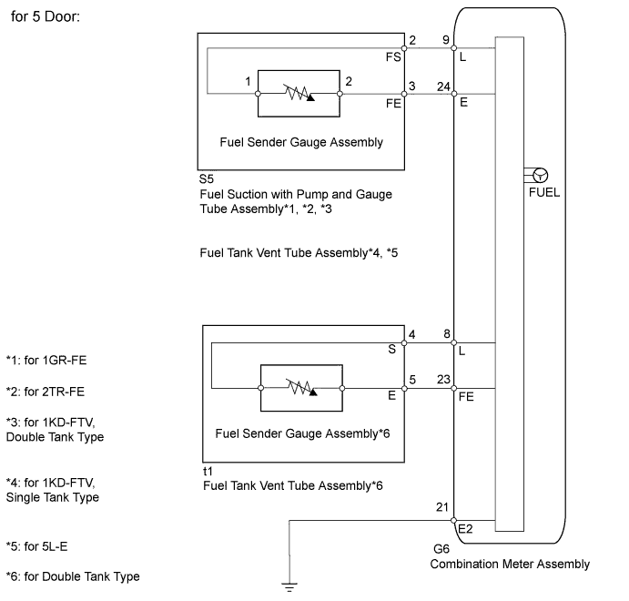
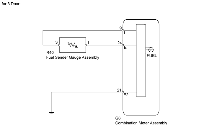
WIRING DIAGRAM
INSPECTION PROCEDURE
PROCEDURE
-
CHECK FOR DTC
-
Check for DTCs Click here.
Result Result Proceed to DTC B1500 or B1501 is not output A DTC B1500 is output B DTC B1501 is output C
B 
GO TO DTC B1500 Click here
C
GO TO DTC B1501 Click here
A 
-
-
PERFORM ACTIVE TEST USING INTELLIGENT TESTER (FUEL METER)
-
Operate the intelligent tester according to the display and select Active Test Click here.
Combination Meter Tester Display Test Part Control Range Diagnostic Note Fuel Meter Operation Fuel receiver gauge EMPTY, EMPTY, INDIC, 1/4, 1/2, 3/4, FULL, FULL Perform the test with the vehicle stopped and engine idling. OK Needle indication is normal.
NG
REPLACE COMBINATION METER ASSEMBLY Click here
OK
-
-
CHECK HARNESS AND CONNECTOR
-
Disconnect the G6 meter connector.
-
Disconnect the S5 gauge connector.
-
Disconnect the t1*1 gauge connector.
-
Disconnect the R40*2 gauge connector.
-
Measure the resistance according to the value(s) in the table below.
Standard Resistance Tester Connection Condition Specified Condition G6-9 (L) - S5-2 (FS) Always Below 1 Ω G6-24 (E) - S5-3 (FE) G6-8 (L) - t1-4 (S)*1 G6-23 (FE) - t1-5 (E)*1 G6-9 (L) - R40-3 (FS)*2 G6-24 (E) - R40-1 (FE)*2 G6-21 (E2) - Body ground G6-9 (L) - Body ground Always 10 kΩ or higher G6-9 (L) - G6-24 (E) G6-8 (L) - Body ground*1 G6-8 (L) - G6-23 (FE)*1
-
1*: for Double Tank Type
-
2*: for 3 Door
-
NG
REPAIR OR REPLACE HARNESS AND CONNECTOR
OK
-
-
CHECK ENGINE TYPE
-
Check the engine type.
Engine Type Engine type Proceed to for 1GR-FE A for 2TR-FE B for 1KD-FTV C for 5L-E D
B 
INSPECT FUEL SUCTION WITH PUMP AND GAUGE TUBE ASSEMBLY (for 2TR-FE) Click here
C
CHECK FUEL TANK TYPE Click here
D
INSPECT FUEL TANK VENT TUBE ASSEMBLY (for 5L-E) Click here
A
-
-
INSPECT FUEL SUCTION WITH PUMP AND GAUGE TUBE ASSEMBLY (for 1GR-FE)
-
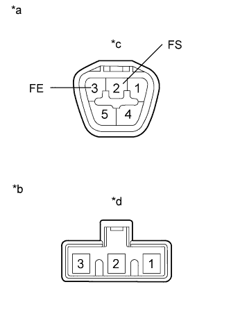
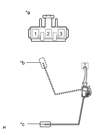
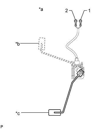
Text in Illustration *a Component without harness connected (Fuel Suction with Pump and Gauge Tube Assembly) *b Lower side (to Fuel Sender Gauge Assembly) *c Connector A *d Connector B Remove the fuel suction with pump and gauge tube assembly.
for 1GR-FE, Single Tank Type: Click here
for 1GR-FE, Double Tank Type: Click here
-
Measure the resistance according to the value(s) in the table below.
Standard Resistance Tester Connection Condition Specified Condition A-2 (FS) - B-2 Always Below 1 Ω A-3 (FE) - B-1 Always Below 1 Ω A-2 (FS) - A-3 (FE) Always 10 kΩ or higher Result Result Proceed to OK A NG (for Single Tank Type) B NG (for Double Tank Type) C
B
REPLACE FUEL SUCTION WITH PUMP AND GAUGE TUBE ASSEMBLY Click here
C
REPLACE FUEL SUCTION WITH PUMP AND GAUGE TUBE ASSEMBLY Click here
A
-
-
INSPECT FUEL SENDER GAUGE ASSEMBLY (for 1GR-FE)
-
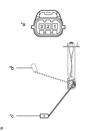
Text in Illustration *a Front view of wire harness connector (to Fuel Sender Gauge Assembly) *b Float Level F (Upper) *c Float Level E (Lower) Measure the resistance according to the value(s) in the table below.
Standard Resistance Tester Connection Condition Specified Condition 1 - 2 Float level is F 12 to 18 Ω Float level is E 405 to 415 Ω Result Result Proceed to OK (for Double Tank Type) A OK (for Single Tank Type) B NG (for Single Tank Type) C NG (for Double Tank Type) D
B
REPLACE COMBINATION METER ASSEMBLY Click here
C
REPLACE FUEL SENDER GAUGE ASSEMBLY Click here
D
REPLACE FUEL SENDER GAUGE ASSEMBLY Click here
A
-
-
INSPECT FUEL TANK VENT TUBE ASSEMBLY (for 1GR-FE, DOUBLE TANK TYPE)
-
Remove the fuel tank vent tube assembly Click here.
-
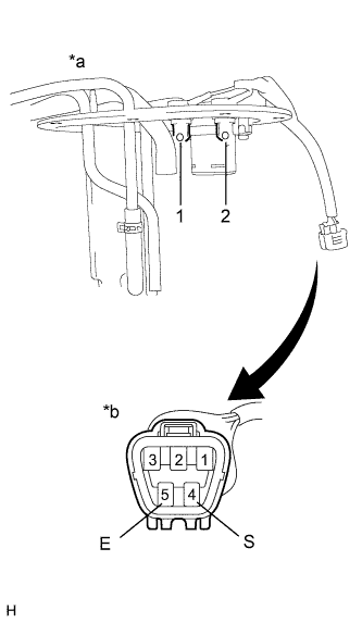
Text in Illustration *a Fuel Tank Vent Tube Assembly *b Component without harness connected (Fuel Tank Vent Tube Assembly) Measure the resistance according to the value(s) in the table below.
Standard Resistance Tester Connection Condition Specified Condition 4 (S) - 1 Always Below 1 Ω 5 (E) - 2 Always Below 1 Ω 4 (S) - 5 (E) Always 10 kΩ or higher
NG
REPLACE FUEL TANK VENT TUBE ASSEMBLY Click here
OK
-
-
INSPECT FUEL SENDER GAUGE ASSEMBLY (for 1GR-FE, DOUBLE TANK TYPE)
-
Remove the fuel sender gauge assembly Click here.
-
Text in Illustration *a Front view of wire harness connector (Fuel Sender Gauge Assembly) *b Float Level F (Upper) *c Float Level E (Lower) Measure the resistance according to the value(s) in the table below.
Standard Resistance Tester Connection Condition Specified Condition 1 - 2 Float level is F 12 to 18 Ω Float level is E 405 to 415 Ω
NG
REPLACE FUEL SENDER GAUGE ASSEMBLY Click here
OK 
REPLACE COMBINATION METER ASSEMBLY Click here
-
-
INSPECT FUEL SUCTION WITH PUMP AND GAUGE TUBE ASSEMBLY (for 2TR-FE)
Note
For 3 door vehicles, proceed to the next step.
-
Remove the fuel sender gauge.
for 2TR-FE, Single Tank Type: Click here
for 2TR-FE, Double Tank Type: Click here
-
Text in Illustration *a Component without harness connected (Fuel Suction with Pump and Gauge Tube Assembly) *b Lower side (to Fuel Sender Gauge Assembly) *c Connector A *d Connector B Measure the resistance according to the value(s) in the table below.
Standard Resistance Tester Connection Condition Specified Condition A-2 (FS) - B-2 Always Below 1 Ω A-3 (FE) - B-1 Always Below 1 Ω A-2 (FS) - A-3 (FE) Always 10 kΩ or higher Result Result Proceed to OK A NG (for Single Tank Type) B NG (for Double Tank Type) C
B
REPLACE FUEL SUCTION WITH PUMP AND GAUGE TUBE ASSEMBLY Click here
C
REPLACE FUEL SUCTION WITH PUMP AND GAUGE TUBE ASSEMBLY Click here
A
-
-
INSPECT FUEL SENDER GAUGE ASSEMBLY (for 2TR-FE)
for 3 door:
-
Remove the fuel sender gauge Click here.
-
Text in Illustration *a Component without harness connected (Fuel Sender Gauge Assembly) *b Float Level F (Upper) *c Float Level E (Lower)
Text in Illustration *a Front view of wire harness connector (Fuel Sender Gauge Assembly) *b Float Level F (Upper) *c Float Level E (Lower) Measure the resistance according to the value(s) in the table below.
Standard Resistance Tester Connection Condition Specified Condition 1 - 3 Float level is F 12 to 18 Ω Float level is E 405 to 415 Ω for 5 door:
-
Measure the resistance according to the value(s) in the table below.
Standard Resistance Tester Connection Condition Specified Condition 1 - 2 Float level is F 12 to 18 Ω Float level is E 405 to 415 Ω Result Result Proceed to OK (for Double Tank Type) A OK (for Single Tank Type) B NG (for Single Tank Type) C NG (for Double Tank Type) D
B
REPLACE COMBINATION METER ASSEMBLY Click here
C
REPLACE FUEL SENDER GAUGE ASSEMBLY Click here
D
REPLACE FUEL SENDER GAUGE ASSEMBLY Click here
A
-
-
INSPECT FUEL TANK VENT TUBE ASSEMBLY (for 2TR-FE, DOUBLE TANK TYPE)
-
Remove the fuel tank vent tube assembly Click here.
-
Text in Illustration *a Fuel tank vent tube assembly *b Component without harness connected (Fuel Tank Vent Tube Assembly) Measure the resistance according to the value(s) in the table below.
Standard Resistance Tester Connection Condition Specified Condition 4 (S) - 1 Always Below 1 Ω 5 (E) - 2 Always Below 1 Ω 4 (S) - 5 (E) Always 10 kΩ or higher
NG
REPLACE FUEL TANK VENT TUBE ASSEMBLY Click here
OK
-
-
INSPECT FUEL SENDER GAUGE ASSEMBLY (for 2TR-FE, DOUBLE TANK TYPE)
-
Remove the fuel sender gauge assembly Click here.
-
Text in Illustration *a Fuel Sender Gauge Assembly *b Float Level F (Upper) *c Float Level E (Lower) Measure the resistance according to the value(s) in the table below.
Standard Resistance Tester Connection Condition Specified Condition 1 - 2 Float level is F 12 to 18 Ω Float level is E 405 to 415 Ω
NG
REPLACE FUEL SENDER GAUGE ASSEMBLY Click here
OK
REPLACE COMBINATION METER ASSEMBLY Click here
-
-
CHECK FUEL TANK TYPE
-
Check the fuel tank type.
Fuel Tank Type Fuel Tank Type Proceed to Single Tank Type A Double Tank Type B
B
INSPECT FUEL SUCTION WITH PUMP AND GAUGE TUBE ASSEMBLY (for 1KD-FTV, DOUBLE TANK TYPE) Click here
A
-
-
INSPECT FUEL TANK VENT TUBE ASSEMBLY (for 1KD-FTV, SINGLE TANK TYPE)
Note
For 3 door vehicles, proceed to the next step.
-
Remove the fuel sender gauge.
for 1KD-FTV, Single Tank Type: Click here
-
Text in Illustration *a Component without harness connected (Fuel Tank Vent Tube Assembly) *b Lower side (to Fuel Sender Gauge Assembly) *c Connector A *d Connector B Measure the resistance according to the value(s) in the table below.
Standard Resistance Tester Connection Condition Specified Condition A-2 (FS) - B-2 Always Below 1 Ω A-3 (FE) - B-1 Always Below 1 Ω A-2 (FS) - A-3 (FE) Always 10 kΩ or higher
NG
REPLACE FUEL TANK VENT TUBE ASSEMBLY Click here
OK
-
-
INSPECT FUEL SENDER GAUGE ASSEMBLY (for 1KD-FTV, SINGLE TANK TYPE)
for 3 door:
-
Remove the fuel sender gauge Click here.
-
Text in Illustration *a Component without harness connected (Fuel Sender Gauge Assembly) *b Float Level F (Upper) *c Float Level E (Lower)
Text in Illustration *a Front view of wire harness connector (Fuel Sender Gauge Assembly) *b Float Level F (Upper) *c Float Level E (Lower) Measure the resistance according to the value(s) in the table below.
Standard Resistance Tester Connection Condition Specified Condition 1 - 3 Float level is F 12 to 18 Ω Float level is E 405 to 415 Ω for 5 door:
-
Measure the resistance according to the value(s) in the table below.
Standard Resistance Tester Connection Condition Specified Condition 1 - 2 Float level is F 12 to 18 Ω Float level is E 405 to 415 Ω
NG
REPLACE FUEL SENDER GAUGE ASSEMBLY Click here
OK
REPLACE COMBINATION METER ASSEMBLY Click here
-
-
INSPECT FUEL SUCTION WITH PUMP AND GAUGE TUBE ASSEMBLY (for 1KD-FTV, DOUBLE TANK TYPE)
-
Remove the fuel sender gauge.
for 1KD-FTV, Double Tank Type: Click here
-
Text in Illustration *a Component without harness connected (Fuel Suction with Pump and Gauge Tube Assembly) *b Lower side (to Fuel Sender Gauge Assembly) *c Connector A *d Connector B Measure the resistance according to the value(s) in the table below.
Standard Resistance Tester Connection Condition Specified Condition A-2 (FS) - B-2 Always Below 1 Ω A-3 (FE) - B-1 Always Below 1 Ω A-2 (FS) - A-3 (FE) Always 10 kΩ or higher
NG
REPLACE FUEL SUCTION WITH PUMP AND GAUGE TUBE ASSEMBLY Click here
OK
-
-
INSPECT FUEL SENDER GAUGE ASSEMBLY (for 1KD-FTV, DOUBLE TANK TYPE)
-
Text in Illustration *a Front view of wire harness connector (to Fuel Sender Gauge Assembly) *b Float Level F (Upper) *c Float Level E (Lower) Measure the resistance according to the value(s) in the table below.
Standard Resistance Tester Connection Condition Specified Condition 1 - 2 Float level is F 12 to 18 Ω Float level is E 405 to 415 Ω
NG
REPLACE FUEL SENDER GAUGE ASSEMBLY Click here
OK
-
-
INSPECT FUEL TANK VENT TUBE ASSEMBLY (for 1KD-FTV, DOUBLE TANK TYPE)
-
Remove the fuel tank vent tube assembly Click here.
-
Text in Illustration *a Fuel Tank Vent Tube Assembly *b Component without harness connected (Fuel Tank Vent Tube Assembly) Measure the resistance according to the value(s) in the table below.
Standard Resistance Tester Connection Condition Specified Condition 4 (S) - 1 Always Below 1 Ω 5 (E) - 2 Always Below 1 Ω 4 (S) - 5 (E) Always 10 kΩ or higher
NG
REPLACE FUEL TANK VENT TUBE ASSEMBLY Click here
OK
-
-
INSPECT FUEL SENDER GAUGE ASSEMBLY (for 1KD-FTV, DOUBLE TANK TYPE)
-
Remove the fuel sender gauge assembly Click here.
-
Text in Illustration *a Fuel Sender Gauge Assembly *b Float Llevel F (Upper) *c Float Level E (Lower) Measure the resistance according to the value(s) in the table below.
Standard Resistance Tester Connection Condition Specified Condition 1 - 2 Float level is F 12 to 18 Ω Float level is E 405 to 415 Ω
NG
REPLACE FUEL SENDER GAUGE ASSEMBLY Click here
OK
REPLACE COMBINATION METER ASSEMBLY Click here
-
-
INSPECT FUEL TANK VENT TUBE ASSEMBLY (for 5L-E)
-
Remove the fuel sender gauge.
for 5L-E, Single Tank Type: Click here
for 5L-E, Double Tank Type: Click here
-
Text in Illustration *a Component without harness connected (Fuel Suction with Pump and Gauge Tube Assembly) *b Lower side (to Fuel Sender Gauge Assembly) *c Connector A *d Connector B Measure the resistance according to the value(s) in the table below.
Standard Resistance Tester Connection Condition Specified Condition A-2 (FS) - B-2 Always Below 1 Ω A-3 (FE) - B-1 Always Below 1 Ω A-2 (FS) - A-3 (FE) Always 10 kΩ or higher Result Result Proceed to OK A NG (for Single Tank Type) B NG (for Double Tank Type) C
B
REPLACE FUEL TANK VENT TUBE ASSEMBLY Click here
C
REPLACE FUEL TANK VENT TUBE ASSEMBLY Click here
A
-
-
INSPECT FUEL SENDER GAUGE ASSEMBLY (for 5L-E)
-
Text in Illustration *a Front view of wire harness connector (to Fuel Sender Gauge Assembly) *b Float level F (upper) *c Float level E (lower) Measure the resistance according to the value(s) in the table below.
Standard Resistance Tester Connection Condition Specified Condition 1 - 2 Float level is F 12 to 18 Ω Float level is E 405 to 415 Ω Result Result Proceed to OK (for Double Tank Type) A OK (for Single Tank Type) B NG (for Single Tank Type) C NG (for Double Tank Type) D
B
REPLACE COMBINATION METER ASSEMBLY Click here
C
REPLACE FUEL SENDER GAUGE ASSEMBLY Click here
D
REPLACE FUEL SENDER GAUGE ASSEMBLY Click here
A
-
-
INSPECT FUEL TANK VENT TUBE ASSEMBLY (for 5L-E, DOUBLE TANK TYPE)
-
Remove the fuel tank vent tube assembly Click here.
-
Text in Illustration *a Fuel Tank Vent Tube Assembly *b Component without harness connected (Fuel Tank Vent Tube Sub-assembly) Measure the resistance according to the value(s) in the table below.
Standard Resistance Tester Connection Condition Specified Condition 4 (S) - 1 Always Below 1 Ω 5 (E) - 2 Always Below 1 Ω 4 (S) - 5 (E) Always 10 kΩ or higher
NG
REPLACE FUEL TANK VENT TUBE ASSEMBLY Click here
OK
-
-
INSPECT FUEL SENDER GAUGE ASSEMBLY (for 5L-E, DOUBLE TANK TYPE)
-
Remove the fuel sender gauge assembly Click here.
-
Text in Illustration *a Fuel Sender Gauge Assembly *b Float level F (upper) *c Float level E (lower) Measure the resistance according to the value(s) in the table below.
Standard Resistance Tester Connection Condition Specified Condition 1 - 2 Float level is F 12 to 18 Ω Float level is E 405 to 415 Ω
NG
REPLACE FUEL SENDER GAUGE ASSEMBLY Click here
OK
REPLACE COMBINATION METER ASSEMBLY Click here
-